Introduction
-
-
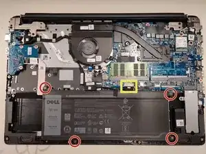
Disconnect the battery cable from the motherboard.
-
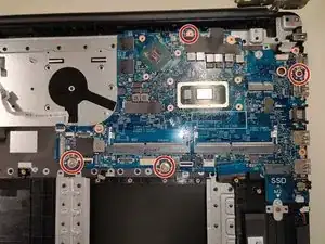
Remove the 4 screws holding it in place
-
Battery can now be removed from device.
-
-
-
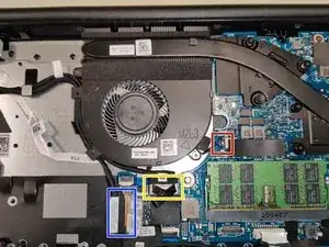
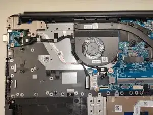
Once these 2 screws are removed the fan will lift out as long as the cables are out of the way.
-
-
-
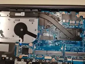
Loosen the 7 screws in sequential order as labeled on the heatsink [1, 2, 3, 4, 5, 6, 7]
-
Lift heatsink out of device
-
To replace these screws: place the heatsink, line up the screw holes, then tighten the screws in the same sequential order labeled on the heatsink.
-
-
-
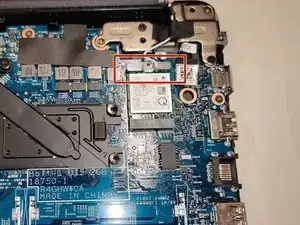
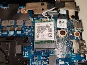
Carefully remove the two antennas from their slots.
-
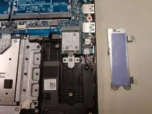
The card should slide right out for easy replacement.
-
-
-
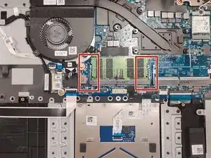
Two clamps hold the RAM module in place, once these are moved the module will slide out of the slot and can be replaced.
-
-
-
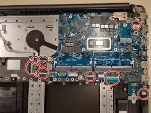
8 remaining connections: IO Board, VGA Board, power button board, display ribbon, touchpad, keyboard, speakers, and PWR.
-
To reassemble your device, follow these instructions in reverse order.
