Introduction

We will show you how to remove the display module which will then allow you to remove the upper case.

  1. H5bBYX1QTDXQvO15
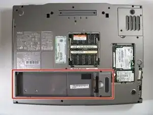
    • Remove the battery from the bottom left of the laptop as shown.

    • Remove the battery before operating on the computer to avoid electrocution.

  2. VPgLiQ5olbRHLJl6
    VPgLiQ5olbRHLJl6
    xGIKAYgQWGSFcWaQ
    bStcnGCCH4xjBtcD
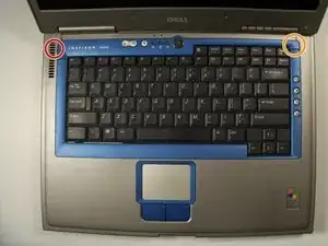
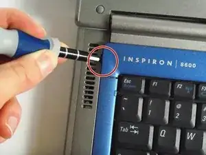
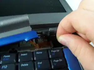
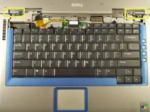
    • Insert a spudger into the notch at the far left side of the top blue panel and pry the hinge cover off.

    • You may need to pry the other side off as well. You can do this by inserting the spudger between the hinge and the top cover.

    • Be careful of the wire attached to the underside of the hinge cover.

  3. NIPNKk6aaYI4lki1
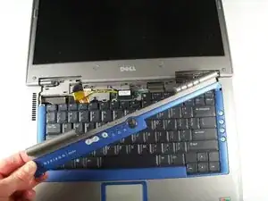
    • Pull the small black tab on the right hand side of the laptop.

    • You have now removed the hinge cover.

  4. dyNFVyTXWXcBtDbr
    dyNFVyTXWXcBtDbr
    woZnEwYinBwiFWum
    BsNTqJWXhDSpvIlh
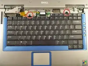
    • Using the Phillips #1 remove the screws at the top of the keyboard as indicated.

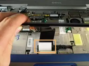
    • Do not just lift up. There is a tab underneath the keyboard that is still connected to the mother board.

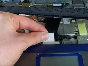
    • You will need to pull out the white tab underneath the keyboard upwards until it pops out of its socket.

    • The keyboard should be easily removable at this point.

  5. ctofAQmWEIoxMS23
    ctofAQmWEIoxMS23
    2lRbJJBWIaafxoLN
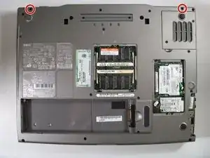
    • Flip the laptop over and remove the indicated screws.

    • Flip the laptop back over.

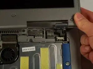
    • Find the two places where the display module is attached to the base of the computer.

  6. FTr5yemRQWJDRKtg
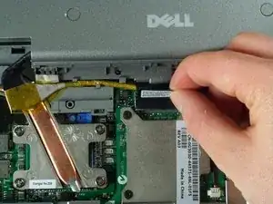
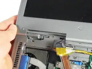
    • Disconnect the video card from the display module by gently lifting upwards on the black tab.

  7. tLmloPXFiMbSwwj3
    tLmloPXFiMbSwwj3
    MRTwOZsSoeAu15Ji
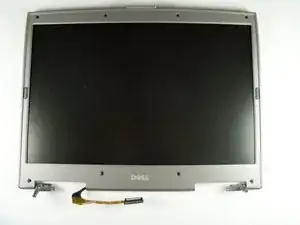
    • Lift the display module directly upwards from the base of the computer.

  8. cbWZoMsNpduhHHTq
    • Now remove the display module.

  9. etTSd4RKfoBilfLW
    etTSd4RKfoBilfLW
    LZS1RhQvMHOaf3CJ
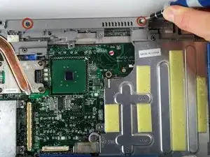
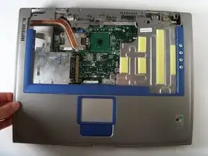
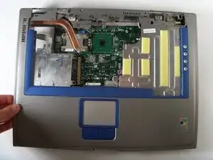
    • Remove the two screws that hold the upper case.

    • You can now pop up the upper case and replace.

    I found that the "upper case" does not come loose this easily. The DELL service manual calls this piece the "palm rest" and includes several other steps, which when followed does allow the piece to be removed. For instance, following removal of the display, the directions go on as follows, with detailed directions:

    3. Remove the display assembly.

    4. Remove the microprocessor thermal - cooling assembly.

    5. Remove the video card .

    6. Remove the 13 M2.5 x 12 - mm screws from the bottom of the computer.

    These instructions can be found at

    ftp://ftp.dell.com/Manuals/all-products/...

    Stanley Hagemeyer -

Conclusion

To reassemble your device, follow these instructions in reverse order.
John Nesthus

Member since: 13/04/11

186 Reputation

0 comments