Introduction

In this guide, we will be showing you how to remove and replace the Display Assembly.

    • Follow the instructions in Before You Begin.

    • Close the display and turn the computer over.

  1. gAMdoaGOsYl3UQBG
    gAMdoaGOsYl3UQBG
    UBwAvwgGKXSOx3G6
    • Loosen the two captive screws that secure the Mini Card compartment cover, then remove the cover and set it aside.

  2. C4OETtkxZBuk56FP
    C4OETtkxZBuk56FP
    MtHXu4YDtjKPPWdv
    • Remove the two M2.5 x 8-mm screws from the bottom of the computer.

  3. mnBRoYNvpiyUMEHB
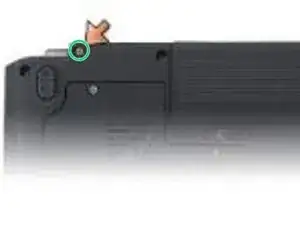
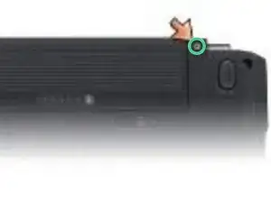
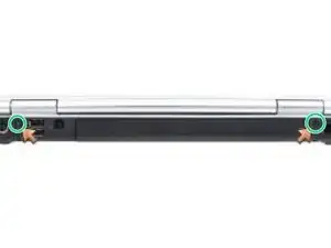
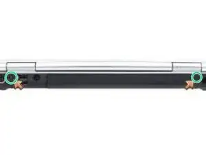
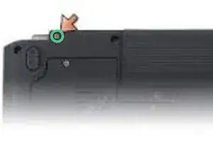
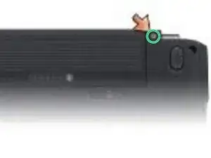
    • Remove the two M2.5 x 8-mm screws from the back of the computer.

  4. dRbkFVeDxuWTYaKS
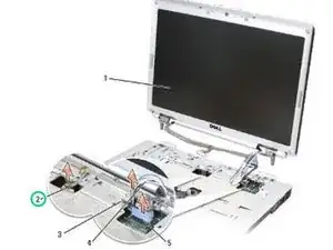
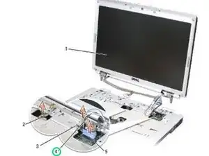
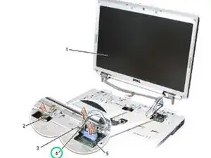
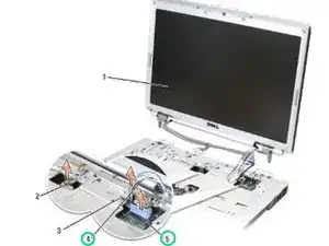
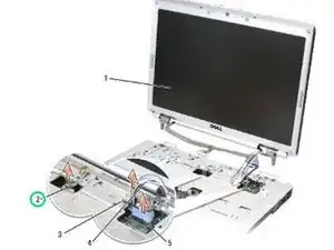
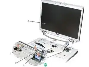
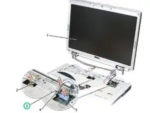
    • Loosen the captive grounding screw, then disconnect the display cable from the display cable connector on the system board.

  5. dmgBFGuFRPAeIDwO
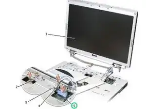
    • Disconnect the camera/microphone cable from the camera/microphone cable connector on the system board.

  6. yFryWSRip5AdZmde
    yFryWSRip5AdZmde
    1pUC3biALJGktthy
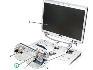
    • Lift the display cable and antenna cables from beneath the tabs on the palm rest.

    • NOTICE: Ensure that the display cable and the antenna cables do not get caught beneath the plastic tabs on the palm rest.

  7. QsfnCpYKaHWymrjQ
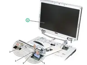
    • Lift the display assembly out of the computer.

    • Align the display hinges with the holes in the base of the computer, then lower the display into place.

  8. gqBxL1HmxRkTmAxL
    • Slide the antenna cables through the hole in the palm rest and the base of the computer.

    • NOTICE: Ensure that the display cable and antenna cables are properly routed and secured beneath the plastic tabs on the palm rest.

  9. RhivfIxpkp5tXwWU
    • Route the display cable and antenna cables beneath the plastic tabs on the palm rest.

  10. xwxAEQPmGODaLkQE
    • Connect the camera/microphone cable to the camera/microphone cable connector on the system board.

  11. LtpNlDFTpMYnjtyT
    • Connect the display cable to the display cable connector on the system board.

  12. kPqtpVjidEw6Y56R
    • Replace and tighten the captive grounding screw.

  13. xvmyhajklVNRD1EF
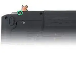
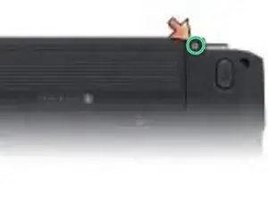
    • Replace the two M2.5 x 8-mm screws on the back of the computer.

    • Close the display and turn the computer over.

  14. VbpfZhu2sVKuBSbc
    VbpfZhu2sVKuBSbc
    ppx5OJXPVMUZTosA
    • Replace the two M2.5 x 8-mm screws on the bottom of the computer.

    • Replace the Mini Card compartment cover and tighten the screws.

Terrence15

Member since: 18/12/17

79034 Reputation

0 comments