Introduction

  1. oPOnIKUeypnxsimi
    • Make sure to turn off and unplug your laptop before starting.

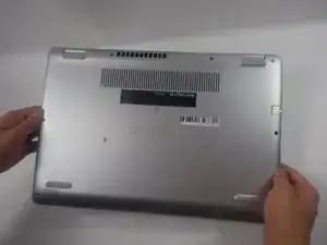
    • Turn over the laptop so that the bottom is facing upwards, and the Inspiron logo is upside-down.

  2. g61NnV56Xi3Ilmeu
    g61NnV56Xi3Ilmeu
    kVDPCFqDOPefTDvL
    QCi5dDrAmYTXtnnH
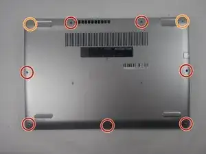
    • Remove the seven 7 mm screws from the bottom using a Phillips #0 screwdriver.

    • Loosen the two captive back corner screws using a Phillips #0 screwdriver.

    • The two corner screws are not removable. A clicking sounds indicates that the screw is fully loosened.

  3. bupImkwfq6wXFZW5
    bupImkwfq6wXFZW5
    MZ4bG4Xqm65cDuKN
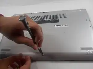
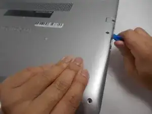
    • Slide an iFixit opening tool underneath the right side USB port and the keyboard.

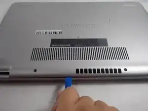
    • Gently trace the iFixit opening tool along the entire outer rim of the laptop, carefully applying an upwards pressure.

    • Be careful not to force open the plate or push too much off without loosening the other sides. This can cause the bottom cover to crack.

  4. BDbtQKm1PpcFMjwT
    BDbtQKm1PpcFMjwT
    LdW2RPYV6dTtETSM
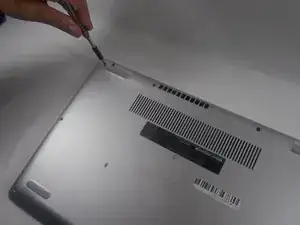
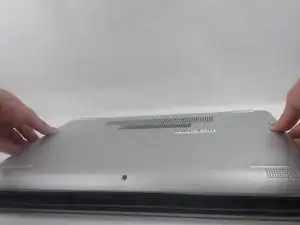
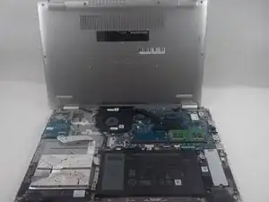
    • Gently pry off the bottom cover from the laptop.

    • Use the iFixit opening tool to loosen any spots you may have missed from Step 3.

  5. URmUC6rTbkIqvkHm
    URmUC6rTbkIqvkHm
    GrBnScvewWLojZEn
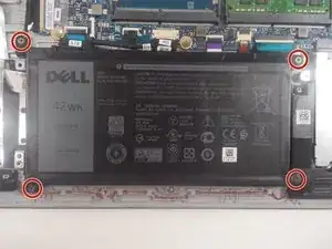
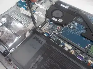
    • Remove the four 3.5 mm screws holding the battery down with a JIS #0 screwdriver.

  6. pp2BxyGd14HSJHrI
    pp2BxyGd14HSJHrI
    mJ5nSuiXR66MiSoW
    kiUKI1SQEeIbxKBV
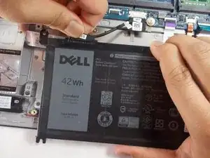
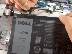
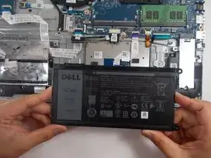
    • Detach the motherboard connector tab from the top left of the battery.

    • Remove the battery from the device.

    • Be sure to carefully wiggle the connector out from the battery socket. Ripping it out too forcefully could damage the socket.

  7. Bgpn5FQw2OYuxc2h
    Bgpn5FQw2OYuxc2h
    yOmqYlTWotW3kaSg
    1ZG1iMgogpekAENI
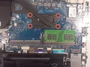
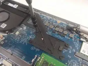
    • Loosen the four captive 3.5 mm screws securing the heat sink to the motherboard using a Phillips #0 screwdriver.

    • Remove the CPU plate cover from the motherboard and safely place it off to the side.

    Some models have three more screws

    Santiago Romero -

  8. LBJoALAgcmovFSan
    LBJoALAgcmovFSan
    PPYc1nDLMQPBAYTF
    Lj6dMWgPMPEVLBYH
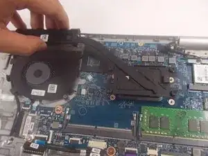
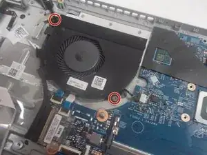
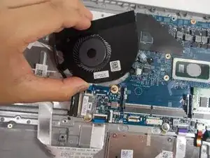
    • Remove the two 3.5 mm screws from the fan with a JIS #0 screwdriver.

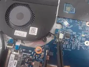
    • Detach the fan connector from the motherboard using a pair of tweezers.

  9. LTTCdpB5LTLeveKP
    LTTCdpB5LTLeveKP
    MbemBIGxBROwujLm
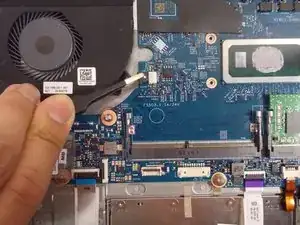
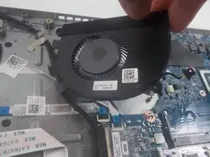
    • Gently lift the fan from the device and de-thread the LCD display cable.

    • Remove the fan from the device.

  10. iVORdPwM24S2EUlQ
    iVORdPwM24S2EUlQ
    XEC6gNBuIcbTNrEF
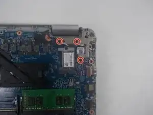
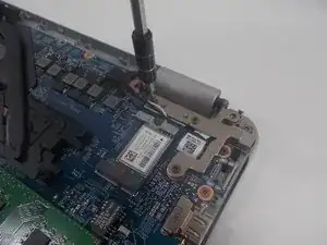
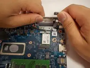
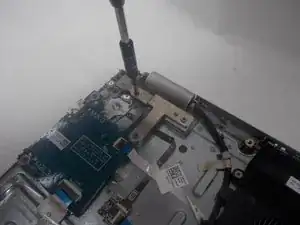
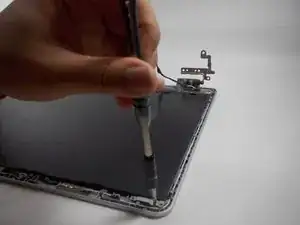
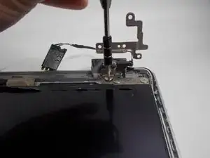
    • Remove the three 6 mm screws holding down the screen hinge in the upper right corner using a JIS #0 screwdriver.

  11. SAWIbvW1eeX2QnHT
    SAWIbvW1eeX2QnHT
    uNMDpWWCN4rUwRLS
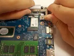
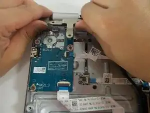
    • Grasp the screen hinge and lift it up.

  12. pcJG2sMcKPiaIcpZ
    pcJG2sMcKPiaIcpZ
    HvK3kbjaSFwHlAlj
    By6kFqSZVhKHOX5u
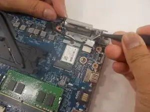
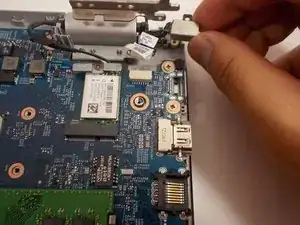
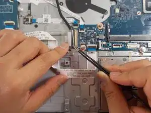
    • Lift up the sticker covering the DC jack connector using tweezers.

    • Using tweezers, detach the motherboard connector and lift the jack out of place.

    • Remove the DC jack from the laptop.

  13. 1mqFUgLvBLev1DQ5
    1mqFUgLvBLev1DQ5
    yN5fSJFqQmgGYwBZ
    jG4Cxbh4eXeQQVio
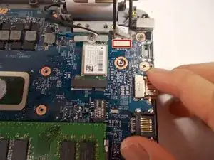
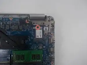
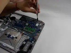
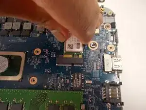
    • Remove the single 3 mm screw that holds down the Wi-Fi card using a Phillips #0 screwdriver.

    • Remove the Wi-Fi card from the motherboard.

  14. fLYqAX3fNIfHilu3
    fLYqAX3fNIfHilu3
    otMEDUnKH1s2usPE
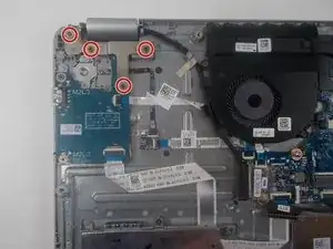
    • Remove the four 6 mm screws from the hinge in the upper left corner with a JIS #0 screwdriver.

  15. dlHBTZqBaXiqMwUt
    dlHBTZqBaXiqMwUt
    Iutfhhds4d4XQTo1
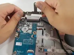
    • Grab the hinge and push upwards.

  16. PONySZusni4i4UCU
    PONySZusni4i4UCU
    14ja12anAKkfi1IT
    LSbgGrH3ASaXoLZI
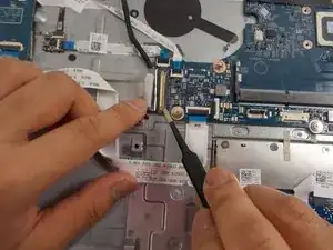
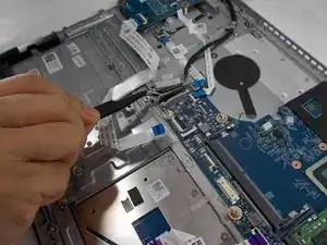
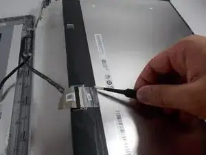
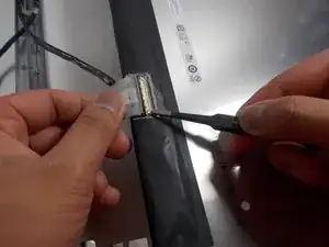
    • Use tweezers to peel off the sticky label covering the display cable port.

    • Use tweezers to unlatch the cable.

    • Grasp the display cable firmly and remove it.

  17. O45eyiTNqcQrCm35
    O45eyiTNqcQrCm35
    FgAHNhiPiJ4gRh6l
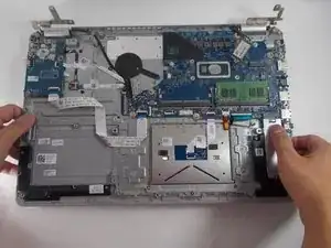
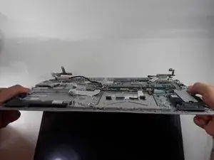
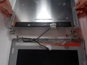
    • Lift the underside of the device and slightly open the laptop.

    • Pull the bottom half of the device off of the hinges.

  18. PATcgKfJSBUDPsf6
    PATcgKfJSBUDPsf6
    h24ELXXKYSvlGOgW
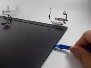
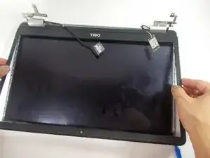
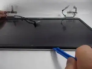
    • Use an opening tool to pry along the edges of the screen from the top plate.

  19. NJdekGkJna4JnjhU
    NJdekGkJna4JnjhU
    IgPeNkECBKiZRwHU
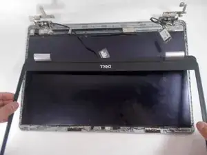
    • Lift and pull the frame from the display.

  20. 4WkL2PNDjE5KM2md
    4WkL2PNDjE5KM2md
    HJbsqtJDJUuYVlOp
    puJy1K1olBBWZOAG
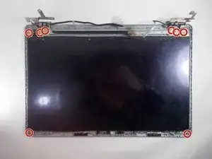
    • Remove the eight 3 mm screws from the screen using a JIS #0 screwdriver.

  21. OSmW12gBAESuYlaT
    OSmW12gBAESuYlaT
    ZPXHB4LnKHBIq1ih
    QftNiUdcpoQFKBpJ
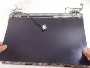
    • Lift the screen and slide it outwards.

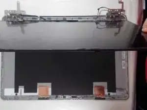
    • Flip over the screen so the back of it is facing upwards.

  22. rgExfWSOarWOOqSC
    rgExfWSOarWOOqSC
    HbBu1CqRGAdtOS6f
    5U3ih5aaD5ZSHCUi
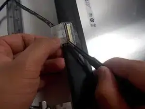
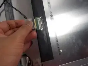
    • Use a pair of tweezers to detach the cable connector from the screen.

  23. HNrLYMip25OFVDGC
    • Grasp the display cable firmly and remove it.

Conclusion

To reassemble your device, follow these instructions in reverse order.
Kristen Gismondi

Member since: 12/11/14

81237 Reputation

0 comments