Introduction
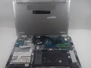
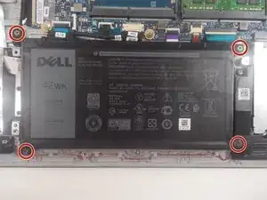
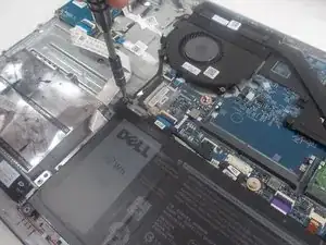
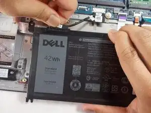
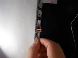
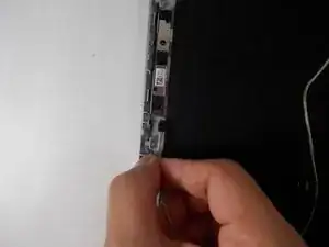
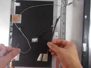
Use this guide to replace the display cable in your Dell Inspiron 15 5584 laptop.
The LCD display cable is a piece of hardware that connects the screen to the motherboard of the device. A broken display cable can cause poor connection between the screen and the motherboard, resulting in distortion, blank areas, or unexpected bands of discoloration.
Because replacement of the LCD cable requires extensive disassembly, confirm that the issue is with the cable before proceeding. If so, ensure the battery is drained and the laptop is shut off and proceed.
Tools
-
-
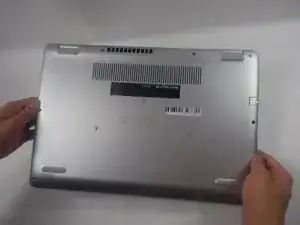
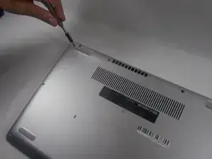
Turn over the laptop so that the bottom is facing upwards, and the Inspiron logo is upside-down.
-
-
-
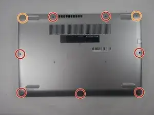
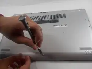
Remove the seven 7 mm screws from the bottom using a Phillips #0 screwdriver.
-
Loosen the two captive back corner screws using a Phillips #0 screwdriver.
-
-
-
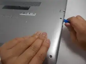
Slide an iFixit opening tool underneath the right side USB port and the keyboard.
-
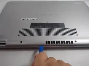
Gently trace the iFixit opening tool along the entire outer rim of the laptop, carefully applying an upwards pressure.
-
-
-
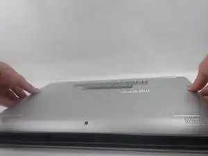
Gently pry off the bottom cover from the laptop.
-
Use the iFixit opening tool to loosen any spots you may have missed from Step 3.
-
-
-
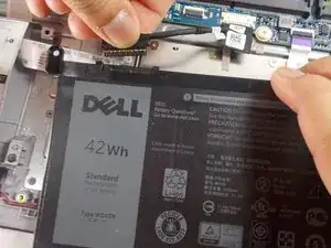
Detach the motherboard connector tab from the top left of the battery.
-
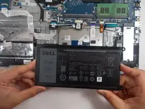
Remove the battery from the device.
-
-
-
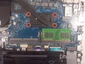
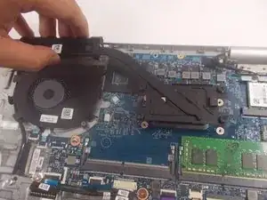
Loosen the four captive 3.5 mm screws securing the heat sink to the motherboard using a Phillips #0 screwdriver.
-
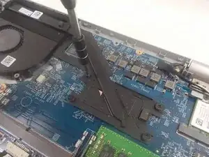
Remove the CPU plate cover from the motherboard and safely place it off to the side.
-
-
-
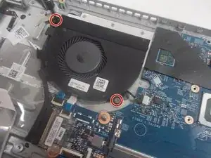
Remove the two 3.5 mm screws from the fan with a JIS #0 screwdriver.
-
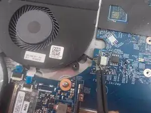
Detach the fan connector from the motherboard using a pair of tweezers.
-
-
-
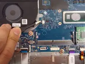
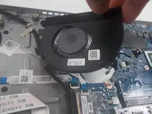
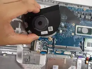
Gently lift the fan from the device and de-thread the LCD display cable.
-
Remove the fan from the device.
-
-
-
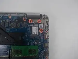
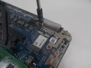
Remove the three 6 mm screws holding down the screen hinge in the upper right corner using a JIS #0 screwdriver.
-
-
-
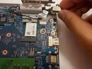
Lift up the sticker covering the DC jack connector using tweezers.
-
Using tweezers, detach the motherboard connector and lift the jack out of place.
-
Remove the DC jack from the laptop.
-
-
-
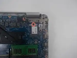
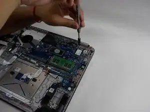
Remove the single 3 mm screw that holds down the Wi-Fi card using a Phillips #0 screwdriver.
-
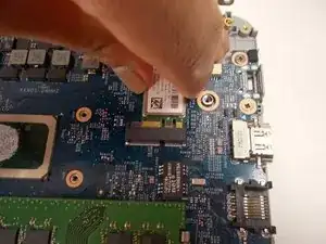
Remove the Wi-Fi card from the motherboard.
-
-
-
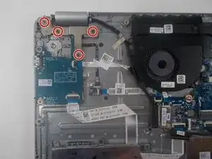
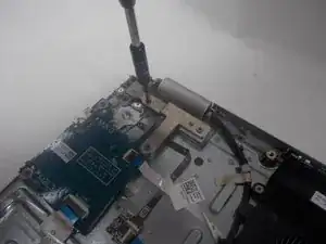
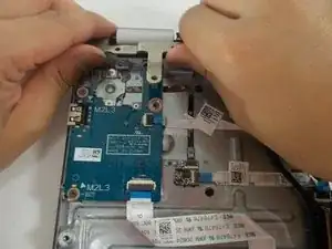
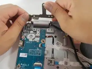
Remove the four 6 mm screws from the hinge in the upper left corner with a JIS #0 screwdriver.
-
-
-
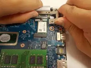
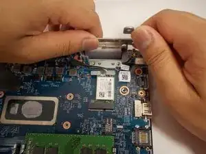
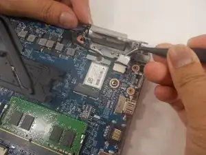
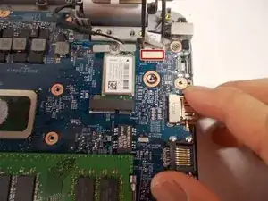
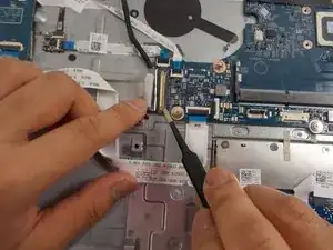
Use tweezers to peel off the sticky label covering the display cable port.
-
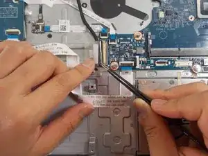
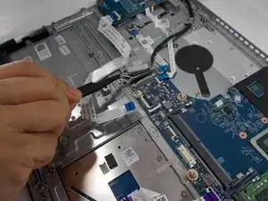
Use tweezers to unlatch the cable.
-
Grasp the display cable firmly and remove it.
-
-
-
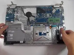
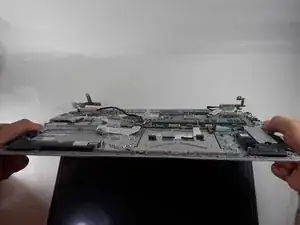
Lift the underside of the device and slightly open the laptop.
-
Pull the bottom half of the device off of the hinges.
-
-
-
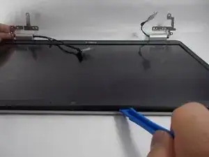
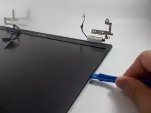
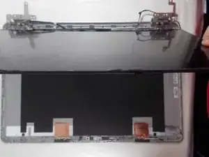
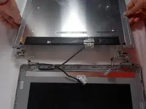
Lift the screen and slide it outwards.
-
Flip over the screen so the back of it is facing upwards.
-
-
-
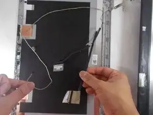
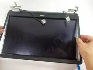
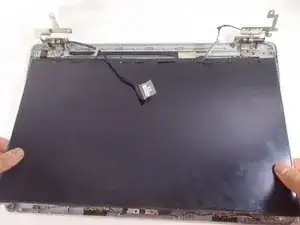
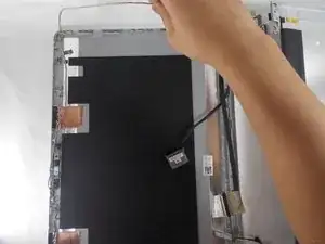
De-thread the wire from the top plate frame.
-
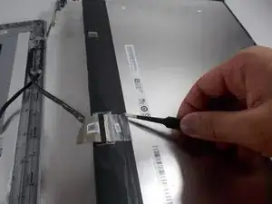
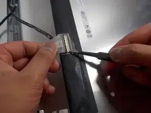
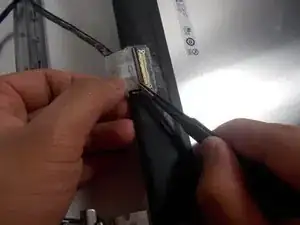
Grasp the connector with tweezers.
-
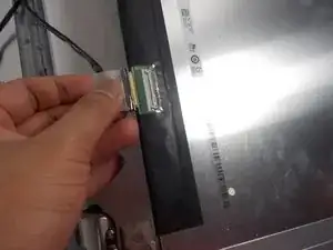
Pull the connector out from the socket.
-
To reassemble your device, follow these instructions in reverse order.
