Introduction

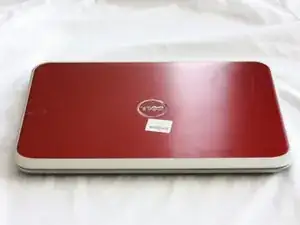
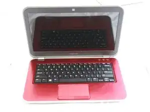
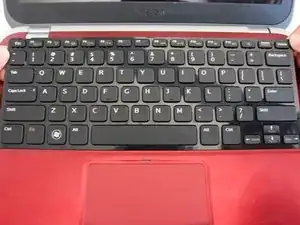
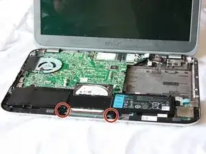
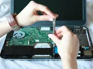
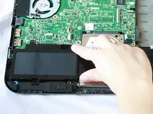
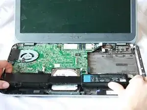
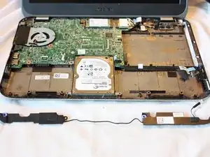
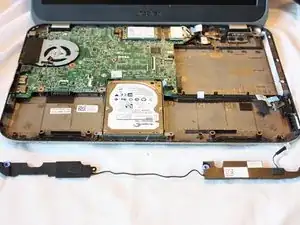
This computer utilizes Skullcandy speakers that are located along the front of the laptop.

  1. NjJqUWeFJg41iaGY
    NjJqUWeFJg41iaGY
    eNw6FKSMlsFlLWQF
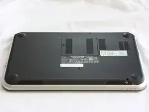
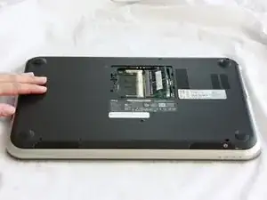
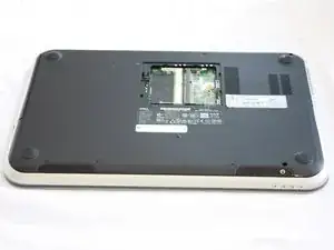
    • Close the display and turn over the computer.

    • Make sure your device is powered down and unplugged before beginning the replacement.

  2. m2WdMOXt3WtO2Xrb
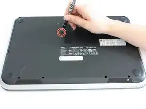
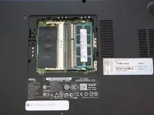
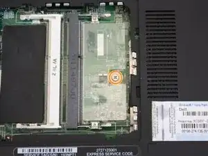
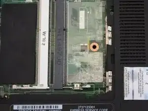
    • Use a J0 bit tipped screwdriver to unscrew the one 6 mm Phillips screw on the RAM cover.

  3. sFZJaXVIjSGuibYV
    sFZJaXVIjSGuibYV
    MFR3Ay1WaGfONyRh
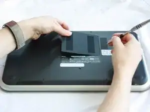
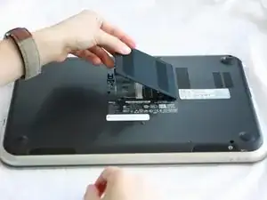
    • Lightly lift the RAM cover up and at an angle, away from the computer.

  4. QtDDZ6kRwVFFKOUD
    QtDDZ6kRwVFFKOUD
    dDDVSdXET5qKNGbN
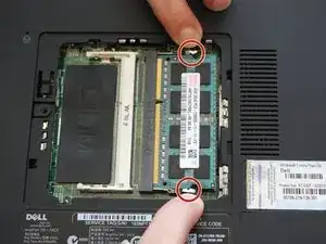
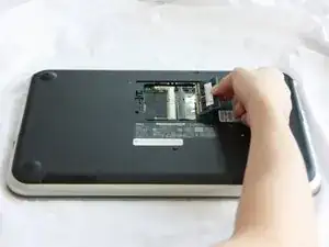
    • Use your fingers to carefully pull the securing clips on the RAM away from each other.

    • The RAM should pop up when the clips are released.

  5. XQRvkFtkTwYK2Gqt
    XQRvkFtkTwYK2Gqt
    DcAN4M35d6klTqpH
    • Remove the popped up RAM by pulling it away from the connection.

    • If it does not pop up pry it out in a steady and straight direction.

  6. kFPhMTqDfeU65V1h
    kFPhMTqDfeU65V1h
    ITwtDQnL4VgIlFDU
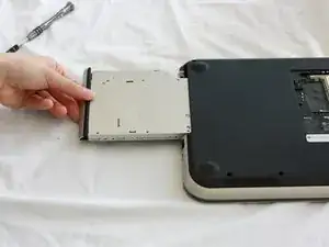
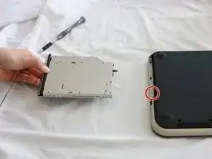
    • Slide the CD/DVD drive on the side of the laptop out using your fingers.

    • Using a J0 bit screwdriver, unscrew the one 2 mm Phillips screw.

    • You only need to unscrew this screw if you are using this as a prerequisite guide.

  7. WSVioDXnhgQSO2FB
    WSVioDXnhgQSO2FB
    tIoHOmbUtr2uDRHl
    JbLSM4RtVdP4baZa
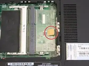
    • Lift the plastic yellow flap on the system board.

    • Use the J0 Bit screwdriver to remove the one 6 mm Phillips screw in center of the system board that is connected to the keyboard.

  8. QmFeT4UYig12Zvlb
    • Flip over the computer and open the display.

  9. J6t1UZINq3HidKyp
    J6t1UZINq3HidKyp
    F2dw2h3uZ6XITnKk
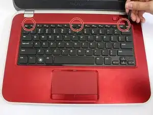
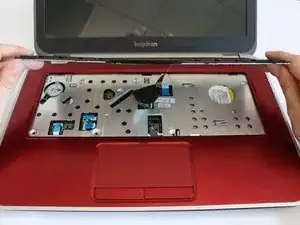
    • Insert a spudger next to the plastic indents located at the top of the keyboard and gently pry to release the securing clips.

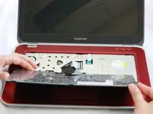
    • Lift the keyboard off of the computer.

    • Be careful not to tear the ribbon that attaches the back of the keyboard to the computer when lifting it.

  10. QVr5RCvxURnibQ4a
    QVr5RCvxURnibQ4a
    V6lI5WbRIjCunQWH
    • Flip the keyboard over onto the palm-rest assembly.

  11. 4EhYVUMPFaeP2t22
    4EhYVUMPFaeP2t22
    o3usPZOkLMvivLyA
    PaRZxyGN5EkyEaVE
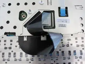
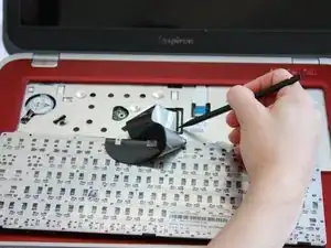
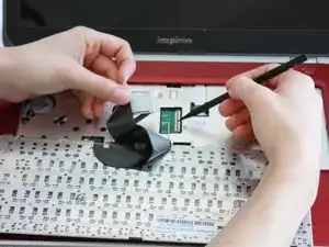
    • Flip the little black securing bar near the base of the ribbon with a spudger to release the ribbon from the computer.

    This description is incorrect. I juist ruïned the keyboard connector. In my laptop there is no black securing bar. Instead, the white connector from the keyboard needs to come out of the black one on the motherboard. This is done horizontally.

    Collin Bootsveld -

  12. 3mrXMtWnrlLRBtCt
    • Close the display and turn over the computer.

  13. 1I6GfJ6Kew5AXg2q
    1I6GfJ6Kew5AXg2q
    p2tpabk62PCnATWK
    wo4QkYPoOl5fcelF
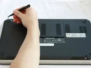
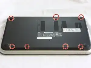
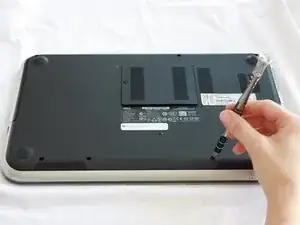
    • Remove all 7 rubber screw caps with tweezers.

    • Use a J0 Bit tipped screwdriver unscrew the seven 6 mm Phillips screws on the back casing of the laptop.

  14. vnWtt5yf65lIGwk3
    vnWtt5yf65lIGwk3
    LSO4CpJ2e2pJsZMy
    • Flip the computer over and open the display.

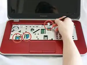
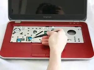
    • Pull on the blue tabs to disconnect the palm rest assembly from the computer.

    Be sure to release the securing bars on each of the ribbon cables before pulling on the blue tabs (similar to the keyboard ribbon cable in step 11).

    ericfogleman -

  15. L3lFAD2V5OFUPnkT
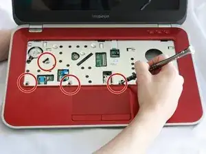
    • Use J0 Bit screwdriver to remove all four 6 mm Phillips screws.

  16. XuWWXRvCfcMMODA4
    XuWWXRvCfcMMODA4
    6IQrylDpLr2p4h5f
    ebeuFFyKKIkvoSEp
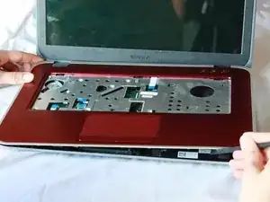
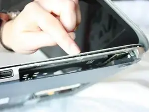
    • Gently wedge the nylon spudger underneath the palm-rest assembly to release the latches.

    • Continue this process on all sides of the computer edges until the assembly pulls off.

    • Remove the palm rest assembly.

    • If you have difficulty lifting up the assembly, you might not have taken out all 7 screws on the bottom of the computer.

  17. rUF5IpcLwCVdCnYI
    rUF5IpcLwCVdCnYI
    L1TrjsQyMiALUTVH
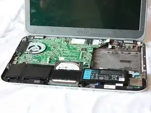
    • Use a J0 Bit screwdriver to remove the two 6 mm Phillips screws securing the battery located near the bottom of the laptop.

  18. AEXTUSc2jgLVxTAw
    AEXTUSc2jgLVxTAw
    kugWS2t6hKZ1tMoT
    UEEpcZ5JxoIYCRTN
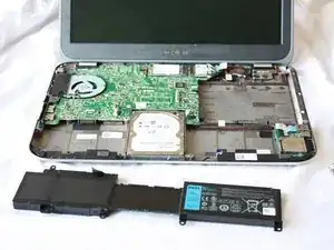
    • Lift the tiny black tab and pull the battery out at a slight angle.

  19. JQTImoxXsPNEhXjJ
    • Locate the black cord that was underneath the battery.

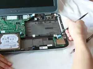
    • Carefully lift up the chip connected to the end of the cord on the daughter board.

    • Use a nylon spudger as leverage if you are having trouble.

  20. qm5MwvcfrKSI26kH
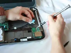
    • Use a J0 Bit screwdriver to remove the two 6 mm Phillips head screw located on the daughter board.

  21. U1ddRjhZmvUIDwPx
    U1ddRjhZmvUIDwPx
    mPKqA32COIkrxdGe
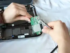
    • Pick the daughter board up and flip it over.

  22. YlM16ydSF4uEnULq
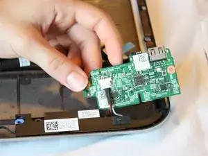
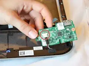
    • Disconnect the black cable from the white connector by pulling the speaker cord from the daughter board.

  23. dFGCLI1UC5MQsBME
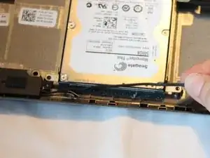
    • Release the wire connecting the speakers from the securing clips by pulling them upward.

  24. wMSuQOucMCwWY1sh
    wMSuQOucMCwWY1sh
    RFqZxxsrI6ZNOWUb
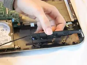
    • Using a rolling motion, remove the speakers from the base of the computer

    • Adhesive foam secures the speakers to the base so you may encounter some resistance.

Conclusion

To reassemble your device, follow these instructions in reverse order.
Diana Shirley

Member since: 12/09/16

122 Reputation

0 comments