Introduction
Use this guide if your screen is cracked or broken in some way.
Tools
-
-
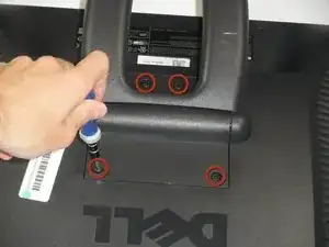
Lay the monitor screen-down so the back screws are exposed.
-
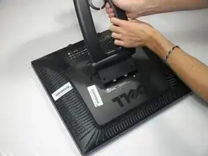
Remove the four 11.9 mm Phillips #2 screws securing the stand to the back of the monitor.
-
-
-
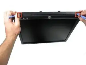
Locate the two holes on the bottom of the monitor.
-
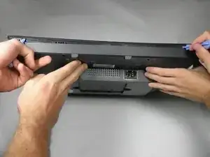
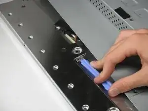
Insert a plastic opening tool or spudger into the holes and gently pry the plastic apart along the groove.
-
Continue prying along the entire edge of the monitor.
-
-
-
When finished prying, the plastic will partially fall away from the rest of the monitor.
-
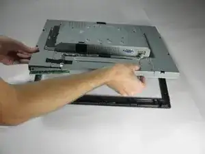
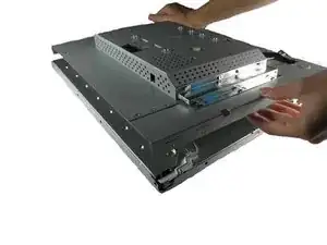
While holding the frames together, carefully flip the monitor over so it faces screen down.
-
Gently lift and remove remove the rear case from the monitor.
-
-
-
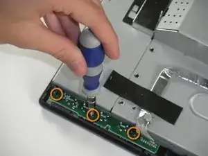
Locate the green interface button board.
-
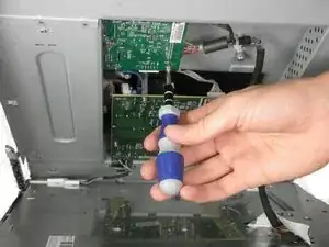
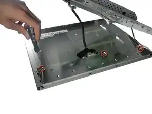
Remove the three 9.71 mm Phillips #2 screws holding the interface button board to the display bezel.
-
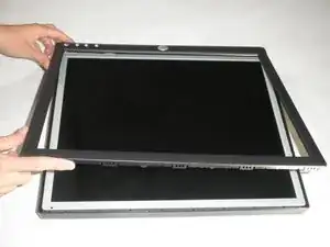
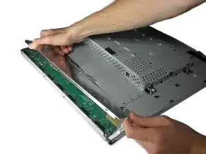
Lift the monitor interior away from the front cover.
-
-
-
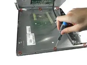
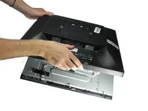
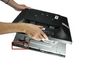
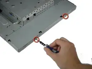
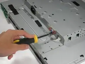
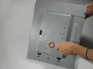
With the monitor facing down, remove the two 5.81 mm Phillips #2 screws on the right side of the metal casing.
-
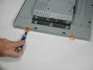
With the monitor still facing down, remove the two 5.81 mm Phillips #2 screws on the left side of the casing.
-
-
-
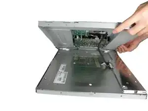
With the monitor facing down, gently lift the back case away from the rest of the monitor to expose the inverter board and mother board.
-
-
-
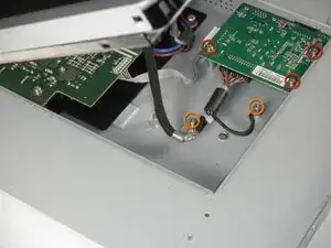
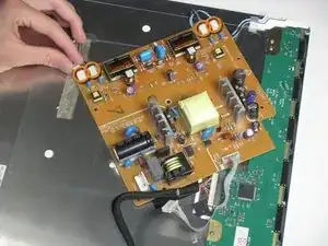
The inverter board is the smaller board in the corner.
-
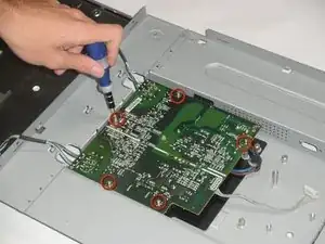
Remove the three 7.69 mm Phillips #2 screws from the inverter board.
-
Remove the two 7.69 mm Phillips #2 grounding screws from the wire with the black connector.
-
-
-
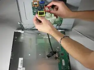
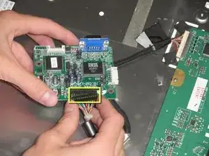
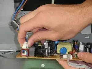
There is a wire connecting the motherboard to the inverter board. Squeeze both sides of the connector and pull to remove it from the socket.
-
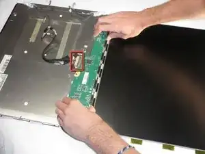
There is another wire connecting the button board to the inverter board. Remove the second white wire connector.
-
A third wire connects the inverter board to the screen circuit board. Remove the black wire connector.
-
The inverter board can now be fully removed.
-
-
-
With the monitor facing down, lift the back cover up and lay it face up, exposing the motherboard.
-
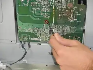
Remove the five 7.7 mm Phillips #2 screws from the motherboard.
-
-
-
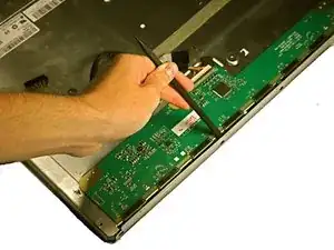
Squeeze the plastic prong in the middle of the motherboard with a metal tweezer, while gently prying the other side with the plastic prying tool.
-
-
-
Remove the connector to the power outlet from the motherboard.
-
Remove the 4 connectors to the metal casing from the motherboard.
-
The motherboard can now be fully removed from the casing.
-
-
-
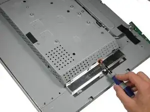
Remove the three 3.94 mm Phillips #00 screws from the metal sheet along the front metal casing.
-
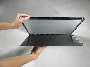
Gently pry the metal sheet away from the metal casing and lift off the metal piece.
-
To reassemble your device, follow these instructions in reverse order.
