Introduction

WARNING : Before working inside your computer, read the safety information that shipped with your computer and follow the steps in Before working inside your computer. After working inside your computer, follow the instructions in After working inside your computer.

Replacing the battery of an Alienware 15 involves removing the memory, solid state drives, and palm rest.

For your safety, discharge your battery below 25% before disassembling your device. This reduces the risk of a dangerous thermal event if the battery is accidentally damaged during the repair. If your battery is swollen, take appropriate precautions.

    • After turning the computer off, close the display and turn the computer over.

  1. jQVMevikXVBIIDIS
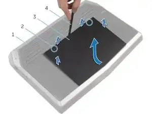
    • After the computer base (#1) is facing up, use a Philips screwdriver to remove the two captive screws (#2) which hold the base panel (#3) down.

    • Then, use a spudger (#4) to lift up the panel. You can also use your fingernail to lift it as well.

    • After the front has been lifted up a bit, the non-screw side of the panel will need to be slid forward a little to finish lifting out the base panel from the computer.

  2. pKt2PMrQkjnENWSg
    • You don't need to disconnect the laptop's battery if you are only replacing the back panel: only perform this step if you will be handling or replacing the electrical components of the computer.

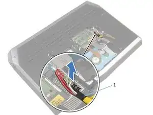
    • Disconnect the battery cable from the system board by pulling up on the battery connector (#1).

    • Turn the computer back over and open the display to the point where you can press the power button.

    • Press and hold the power button for 4 seconds to ground the system board so that you can safely remove components such as the RAM.

  3. fm1TgXXouUDSfYGA
    • WARNING: Before working inside your computer, read the safety information that shipped with your computer and follow the steps in Before Working Inside Your Computer. After working inside your computer, follow the instructions in After Working Inside Your Computer.

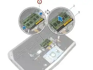
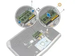
    • Using your fingertips, carefully spread apart the securing clips on each end of the memory-module slot until the memory module pops up.

    Is this ESD (electrostatic safety discharge )do you have to have some kind of device on you to discharge electrostatic and also do you have the back up your memory on your computer? before taking these board chips out.

    Dave -

  4. eQAFQY3g1dMuD3gf
    • Slide and remove the memory module from any memory-module slots that you would like to repopulate.

  5. 1AsRtqvIyEKNHvXV
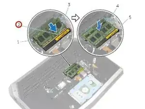
    • Align the notch on the New memory module with the tab on the memory- module slot.

  6. YXTSgKFngspQcjcQ
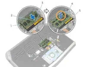
    • Slide the memory module firmly into the slot at an angle and press the memory module down until it clicks into place. Do this individually for each memory module that is replaced.

    • NOTE : If you do not hear the click, remove the memory module and reinstall it.

  7. OZDf3DurR6X3sTpu
    • WARNING: Before working inside your computer, read the safety information that shipped with your computer and follow the steps in Before Working Inside Your Computer. After working inside your computer, follow the instructions in After Working Inside Your Computer.

    • CAUTION : Solid-state drives are fragile. Exercise care when handling the solid-state drives, and avoid touching the gold contact pins.

    • CAUTION : To avoid data loss, do not remove the solid-state drive while the computer is in sleep or on state.

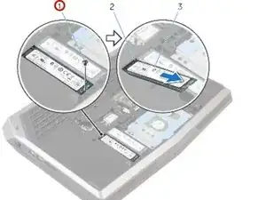
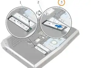
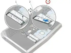
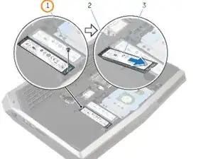
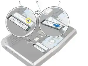
    • Remove the screw that secures the solid-state drive to the computer base.

  8. 4aJi2YxPocXJRYJ5
    • Slide and remove the solid-state drive from the solid-state drive slot.

  9. lTKCemcZ31IBgJix
    • Slide the solid-state drive into the solid-state drive slot.

  10. mkHN6UTSuFA24AiX
    • Align the screw hole on the solid-state drive with the screw hole on the computer base.

  11. QEbdwbTc2MHsINdX
    • Replace the screw that secures the solid-state drive to the computer base.

  12. XHkMiVLHo6GR2cl3
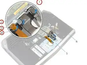
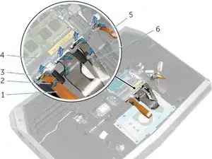
    • Remove the keyboard-backlight cable, keyboard cable, and macro-keys cable from the routing guides (the small plastic tabs) on the computer base.

    • Do not force the cables out of the system board without lifting up the latches that hold them down first. Forcing out cables could result in them snaping or tearing, rendering them unusable.

    • You do not need to remove the hard drive to remove the battery, but it is advisable that you do so if you are concerned about dropping the computer while removing the battery.

  13. 26xtTLg5iIMZrho1
    • Carefully lift the white latches (like #3) and remove all 4 of the keyboard and macro-key cables from their sockets.

    • Don't forget to lift the smaller black latch and remove the macro-key backlight cable (#5) to the right of the other cables!

  14. NmglBLxBEnvtsdXY
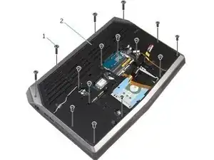
    • Remove all 15 screws which hold down the computer base. Two screws are located near the RAM slot, while the others are situated mostly around the outside of the computer.

  15. iXCyXBbhEwf1ufBa
    iXCyXBbhEwf1ufBa
    S4movhiKfnXjMDMM
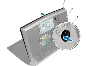
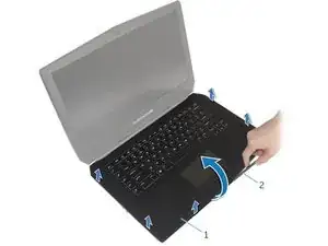
    • Open the computer's display and lay the computer down on the back of its open display.

    • Using your finger or a screwdriver, push inside the palm rest release hole (#3 in image 1) to release the palm rest from the tabs that hold it down.

    • Using a plastic scribe, pry up along the edges of the palm-rest assembly. After the palm rest is no longer attached to the computer via any tabs, try lifting up the palm-rest assembly.

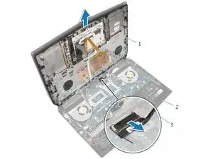
    • Make sure that no cables or other fragile objects are still attached to the palm-rest assembly as you pull it out.

  16. dmihdgulFI1MdhJD
    • If you are only replacing the battery, you do not need to perform this step.

    • Pull the power-button cable horizontally to remove it from the palm rest assembly.

  17. wHGiImRwal6ItiWj
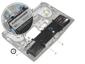
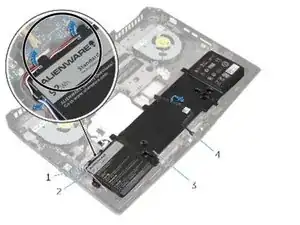
    • Remove the speaker cable from the routing guides on the battery.

    • Note the front AlienFX LED cable routing and peel off the cable from the battery.

  18. GZihiRyMW5USUnus
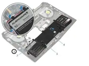
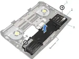
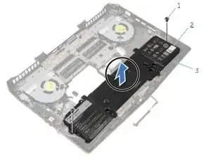
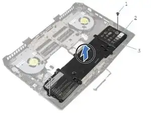
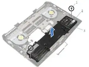
    • Remove the screws that secure the battery to the computer base.

  19. JytH4oAQ2FxPV1QU
    • Lift the battery off the computer base.

  20. GXkZHoeamCSEeVgu
    • Align the screw holes on the battery with the screw holes on the computer base.

  21. dUaeKLZmWOEc5XZG
    • Replace the screws that secure the battery to the computer base.

  22. LqBkviFFGS1WqIho
    • Adhere the front AlienFX LED cable to the battery.

  23. WwQa1uZwxmAKiMXb
    • Route the speaker cable through the routing guides on the battery.

Conclusion

To reassemble your device, follow these instructions in reverse order.

Johnathan Hammond

Member since: 28/02/18

44820 Reputation

2 comments

This is the Alienware 13 not the 15

Bradley De Souza -

in what way does it look like 13? dumbass

Rahul S -