Introduction

In this guide, we will be showing you how to remove and replace the Touch Pad.

  1. CDsuOyUt4xSBGJju
    • WARNING: Before working inside your computer, read the safety information that shipped with your computer and follow the steps in Before Working Inside Your Computer. After working inside your computer, follow the instructions in After Working Inside Your Computer.

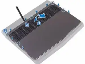
    • Loosen the five captive screws that secure the base cover to the computer base.

  2. DFmUSOI1LuVa6jag
    • Using a plastic scribe, gently pry the base cover to release the tabs on the base cover from the slots on the computer base.

  3. LQltbZTtjyoNwsEQ
    • Lift the base cover off the computer base.

  4. t5MXEC6enUskXQXq
    • Using a plastic scribe, disconnect the battery cable from the system board.

    • Press and hold the power button for five seconds to ground the system board.

    • Connect the battery cable to the system board.

  5. Vx31thWG3rueqP2K
    • Slide the tabs on the NEW base cover into the slots on the computer base and snap the base cover into place

  6. aH3ugbqIEuosxgsu
    • Tighten the five captive screws that secure the base cover to the computer base.

  7. 4wdEMnX3Xdg2OdVD
    • WARNING: Before working inside your computer, read the safety information that shipped with your computer and follow the steps in Before Working Inside Your Computer. After working inside your computer, follow the instructions in After Working Inside Your Computer.

    • CAUTION: To avoid damaging the wireless card, do not place any cables under it.

    • Remove the screw (M2x3) that secures the wireless card and bracket to the computer base.

  8. NKN2ZgrTGfVpbIpf
    • Lift the wireless-card bracket off the wireless card.

  9. oWGCj3GO6JBN4iYU
    • Disconnect the antenna cables from the wireless card.

    • CAUTION: To avoid damaging the wireless card, do not place any cables under it.

    • Align the notch on the wireless card with the tab on the wireless-card slot.

    • Slide the NEW wireless card at an angle into the wireless-card slot.

    • Connect the antenna cables to the wireless card.

  10. xGOuAVKQrv6lakkK
    • Align the screw hole on the wireless-card bracket with the screw hole on the wireless card and the computer base.

  11. 2L2JlQxhAk2fDORt
    • Replace the screw (M2x3) that secures the wireless-card bracket to the wireless card and the computer base.

  12. GKvkbggsOeXboNLl
    • WARNING: Before working inside your computer, read the safety information that shipped with your computer and follow the steps in Before Working Inside Your Computer. After working inside your computer, follow the instructions in After Working Inside Your Computer.

    • Remove the screw (M2x3) that secures the solid-state drive to the computer base.

  13. VKQYHlGoI2j2LH6C
    • Lift and slide the solid-state drive from the solid-state drive slot.

    • Align the notch on the NEW solid-state drive with the tab on the solid-state drive slot and slide the solid-state drive into the solid-state drive slot.

  14. LqUfvk4VGLQAjBBb
    • Press the memory module down until it clicks into place.

  15. 6UyqMw2LPEPoRKVN
    • Remove the two screws (M2.5x6L) that secure the rear-I/O cover to the palm-rest assembly.

  16. 2kMjscXrEQN6aBVr
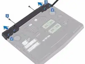
    • Using a plastic scribe, gently release the tabs that secure rear-I/O cover to the computer base.

    • Slide and remove the rear-I/O cover from the computer base.

  17. peJQ2EKGfciJWi5J
    • Slide the NEW rear-I/O cover into the slots on the computer base and snap the rear-I/O cover into place.

    • Replace the two screws (M2.5x6L) that secure the rear-I/O cover to the palm-rest assembly.

  18. INhC6txjkWOFAbiZ
    • WARNING: Before working inside your computer, read the safety information that shipped with your computer and follow the steps in Before Working Inside Your Computer. After working inside your computer, follow the instructions in After Working Inside Your Computer.

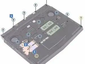
    • Remove the eleven (M2.5x6L) screws that secure the computer base to the palm-rest assembly.

  19. PkbaxpEoy1Oh1LKi
    • Remove the (M2x3) screw that secures the computer base to the palm-rest assembly.

  20. 5LJ4E4qu5KQpRoct
    • Remove the two (M2.5x6L) screws that secure the computer base to the palm-rest assembly.

  21. RpyaaNfBsDc4nJfB
    • Lift the computer base from the palm-rest assembly.

  22. e5IFHbxXyViEAjX5
    • Align the screw holes on the NEW computer base with the screw holes on the palm-rest assembly.

    • Replace the two (M2.5x6L) screws that secure the computer base to the palm-rest assembly.

    • Replace the (M2x3) screw that secures the computer base to the palm-rest assembly.

    • Replace the eleven (M2.5x6L) screws that secure the computer base to the palm-rest assembly.

  23. Q66rS5FbS3PQTJHX
  24. YFl4yajiElFSPjlw
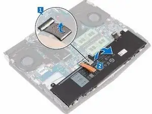
    • Lift the battery off the palm-rest assembly.

  25. bJvnMXiGeBeFgpc4
    • CAUTION: Ensure the keyboard and keyboard-backlit cables are not under the battery.

    • Using the alignment post, place the NEW battery on the palm-rest assembly.

  26. fSP3NNoxlTx5tolO
    • Adhere the keyboard connector that secures the battery to the palm-rest assembly.

  27. 66rijjPEu5yvYlIs
    • WARNING: Before working inside your computer, read the safety information that shipped with your computer and follow the steps in Before Working Inside Your Computer. After working inside your computer, follow the instructions in After Working Inside Your Computer.

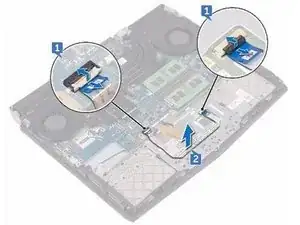
    • Open the latches and disconnect the touch-pad cable from the system board and touch pad.

  28. 6HdwrHcdcu21NweF
    • Peel off the touch-pad cable from the touch-pad bracket.

  29. snxpgjEbXqfOOdWe
    • Open the latch and disconnect the touch-pad buttons cable from the touch pad.

  30. uVCtsKmGpUpaR2Ov
    • Remove the five screws (M2x3) that secure the touch-pad bracket to the palm-rest assembly.

  31. irVhsNBBRpZM11ai
    • Using a plastic scribe, lift the touch-pad bracket off the palm-rest assembly.

  32. 16EWRY5M4T3Hc6TM
    • Lift the touch pad off the palm-rest assembly.

  33. tfB1IKZKRbgK5QJW
    • CAUTION: Ensure the keyboard and keyboard-backlit cables are not under the touch pad.

    • Using the alignment posts on the palm-rest assembly, place the NEW touch pad on the palm-rest assembly.

  34. w4nWdhDYIcC2V3ux
    • Align the screw holes on the touch-pad bracket with the screw holes on the palm-rest assembly.

    • Replace the five screws (M2x3) that secure the touch-pad bracket to the palm-rest assembly.

    • Slide the touch-pad buttons cable into the respective connector on the touch pad and close the latch to secure the cable.

    • Slide the touch-pad cables into their respective connectors on the system board and touch pad, and close the latches to secure the cable.

Conclusion

To reassemble your device, follow these instructions in reverse order.
Terrence15

Member since: 18/12/17

79034 Reputation

0 comments