Introduction
I'll start the guide where the Dell service manual ends removing the display assembly. The fully developed screen is therefore a prerequisite. There are already instructions for this.
The aim of this guide is to replace the TFT display. It's not just the display assembly that should be replaced, but the TFT. The lid and the other components are retained. The display is a Sharp model, exactly the model that was installed as an original part. The TFT now has a lot of dead pixels and is therefore being replaced.
Caution: Not for beginners or somebody with ten thumbs. However, you can save a lot of money. The assembly is available for around €500 to €600, the display for €120
Replacing the display would not have been possible without the XPS 13 teardown. You can't get a display without a glass pane out without the cutting thread. I would almost bet :-) Thank you for the crucial hint!
Tools
Parts
-
-
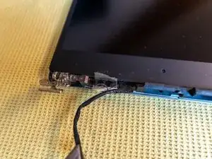
Slide the WiFi antenna cover (between the hinges) to the right until it rests against the right hinge. It takes some strength to do that. Lift cover and set aside.
-
-
-
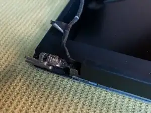
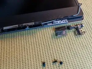
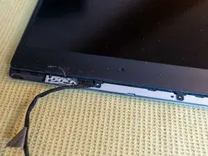
under the black tape are three screws. Unscrew these screws and the hinge can be loosened. Place the hinge and screws in a small bowl.
-
-
-
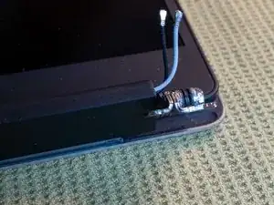
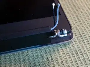
The WiFi antenna is attached with four screws. Unscrew the screws, place the antenna and screws in a bowl.
-
-
-
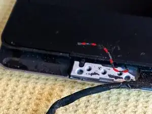
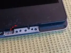
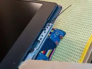
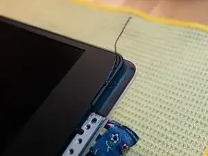
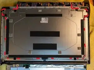
One end of the same thread can be found near the screw holes of the hinges. The thread runs around between the cover and the TFT. The thread is marked in red here. It can also lie hidden in the depression, then fish out.
-
-
-
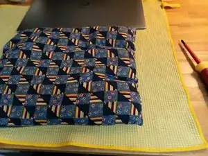
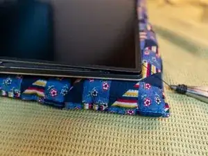
The lid has to be heated up a lot because the TFT is glued. The glue will soften when the heat is there. The lid is made of metal, it takes time for the heat to emit to the inside. I used a seed pillow, or two next to each other. You can certainly use other methods...
-
-
-
The right thread is pulled out. The thread has to be pulled around obstacles (plastic nose) from time to time. A plectrum or a wooden spatula can help to lift the display slightly. Then the thread has more space.
-
-
-
The thread cuts the adhesive strip behind the TFT along the narrow side. I wrapped the thread around the pliers so that you can apply the necessary pull. Only cut up to the upper long side. There is no glue on the long side. Do the same on the other side. Insert spacers, otherwise the TFT will stick again.
-
-
-
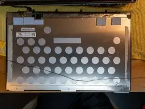
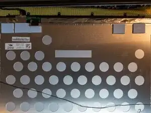
The TFT can be removed. On the inside of the lid you can see the guides for the thread. The cut adhesive strips can be seen on the display.
-
Second photo: The cutting thread is on the display. A good idea from the developers at Dell :-). If you really want it to stick.
-
-
-
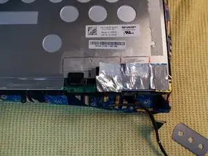
Carefully remove the heat-conducting pad with a blade and place it on a foil. Mark the position of the cushions.
-
-
-
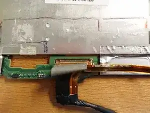
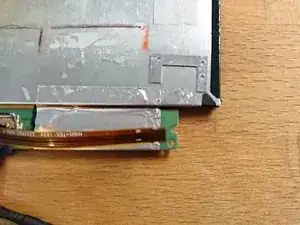
Remove the adhesive tape over the display connector. Fold down the brackets, pull the plug outwards. Unplug the camera connection cable. Detach the camera connection point (warm it up).
-
-
-
Carefully peel off the attached camera. IMPORTANT! The camera has to be glued back to the new display in exactly the same place. The hole in the display frame is small.
-
-
-
Important! The camera needs to be put back in very exactly the same place on the new display.
-
-
-
This was the most annoying step for me. The thin aluminum frame is attached to the TFT with a lot of adhesive. The glue is very strong. A lot of heat helps here again. Warning: The thin frame must not be bent. He can certainly break too. Carefully remove piece by piece and place pieces of wood in between
-
-
-
The frame must be freed from all adhesive residues. Don't scratch the inner edge, otherwise you'll see it later because it's no longer black...
-
-
-
If you want to take the risk of not getting the lid out, you can save yourself this. I put the thread back in the groove it was in. The thread is very important to me. There are stickers that hold the thread in place.
-
-
-
Check everything again. Do not remove the foil from the adhesive tape yet. Try inserting the display. Put on the display frame as a test. Can the camera be seen through the hole in the frame? Are the ends of the threads in the right place? If everything is correct, go to step 22
-
-
-
Remove the protective film from the adhesive tape. Insert the tabs of the display at the top of the lid, lower the display.
-
-
-
I put double sided tape on the back of the frame. Black tape would be ideal. I didn't want to use liquid glue or Sikaflex, so only double-sided tape was an option. There shouldn't be any tape sticking out, I used a sharp blade to cut it.
-
-
-
Remove the protective film from the adhesive tape and glue the frame in place. Press firmly all around.
-
-
-
I save myself the further instructions. Reassemble all components to the lid and screw the display assembly into place. From here use the Dell service manual again and be happy with the new display without dead pixels.
-
Another device saved that has enough power even by today's standards and can still be used for years to come
-
Follow the steps in reverse order to reassemble your device.
