Introduction
Tools
-
-
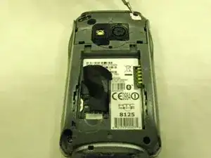
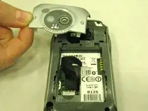
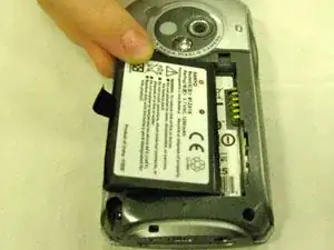
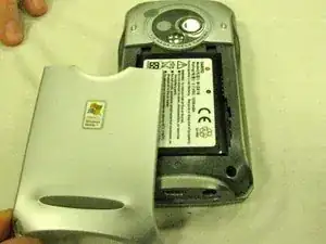
Hold the phone with the back (camera side) facing you. Slide the battery cover off of the phone.
-
-
-
Unscrew the four black Torx head screws, found in each corner of the back.
-
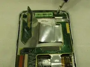
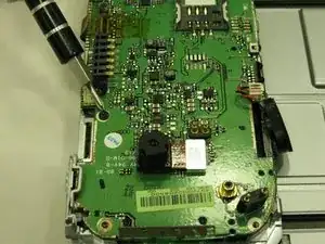
Warning: Unscrewing the screw indicated in the picture will void any warranty on the phone.
-
-
-
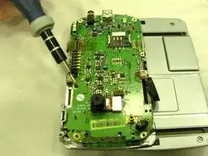
After removing the screw, pull up on the motherboard to release it from the circuit board (green tab, see Figure 11). This will simply snap out, and does not require too much force.
-
-
-
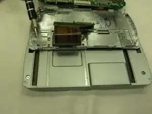
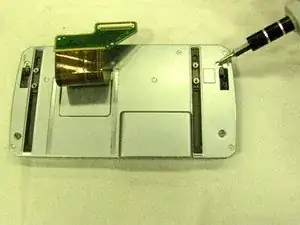
Remove the keyboard by unscrewing the two pairs of silver Torx head screws that run along the sliding tracks.
-
-
-
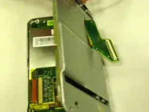
Use the light blue wedge tool to remove the back. The circuit board will slide out of the slot and will stay attached to the remaining front half of the phone.
-
-
-
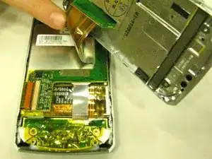
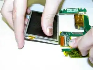
Remove the circuit board; pull it apart at the orange tab. This will detach the screen from its circuit board.
-
-
-
Attach the new screen by aligning the orange tab with the beige rectangle on the circuit. Secure by pushing down on the bronze piece.
-
-
-
Screw the four smallest silver Torx head screws into the circuit board, which will attach it to the front cover.
-
-
-
Use the four Phillips head silver screws to attach the back piece to the front of the phone.
-
-
-
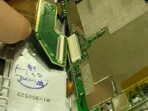
Attach the motherboard to the circuit board, aligning the two white rectangles until they snap into place. Lay motherboard into place.
-
-
-
Secure the motherboard by screwing the small black Phillips head screw into place, located below the right speaker. Note: You may need to remove the right speaker in order to replace this screw.
-
-
-
Secure the back cover by screwing the four long, black Torx screws into the four corners of the back cover.
-
To reassemble your device, follow these instructions in reverse order.

