Introduction

  1. dOHP2yiGosIHkLSI
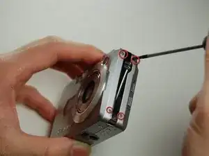
    • With your Phillips #00 screwdriver, remove the four screws on the side of the camera.

  2. PGD3P1bMd1HiEDTZ
    • With a Phillips #00 screwdriver, remove the four screws located on the bottom of the camera.

    • The bottom screws are longer than the top screws, so label accordingly for easy reassembly.

  3. 21aHStBG2jTcCveP
    • With a Phillips #00 screwdriver, remove the four screws on the opposite side of the camera.

  4. lLokhgxVKwEJaSMQ
    lLokhgxVKwEJaSMQ
    XwSf3eHZAmTlaR1C
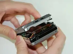
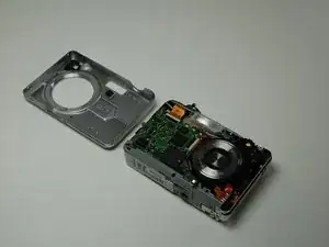
    • Once all screws have been removed, gently pry open bottom casing.

    • With tweezers, carefully remove the ribbon from the LCD screen.

    • Set bottom casing aside.

    • Prying open the camera from the casing could potentially damage the device, so open the casing slowly.

  5. ndFMsRgYjaRorKUc
    ndFMsRgYjaRorKUc
    aQao1GLtZQSWYQnD
    A6NQBv1jsKAYG2HD
    • Using tweezers, gently pry apart the top casing from the camera.

    • Set the top casing aside.

  6. ynLNnilxf3OXZcji
    ynLNnilxf3OXZcji
    exwf1TArvDqYtJvI
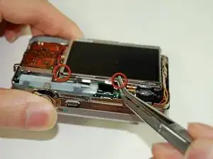
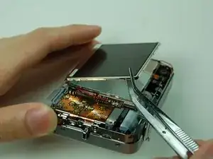
    • Use tweezers to pry the LCD screen off from the opening.

    • The bottom of the LCD screen is attached to the frame by a few pieces of black tape.

  7. xt1cZyvkeRS4LBKM
    xt1cZyvkeRS4LBKM
    HAZECarTwsnLIZ1o
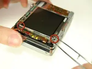
    • Use tweezers to lift up the LCD screen away from the camera.

    • Moving the screen could potentially damage the wire connecting it to the camera, so move the LCD screen slowly.

  8. NBG5WrULoO6AOjA5
    NBG5WrULoO6AOjA5
    vGUYE1jBmOYObSqm
    • Use tweezers to slowly pry off LCD casing by lifting and moving it off the camera.

  9. uPULtl6vy6vDNTiK
    uPULtl6vy6vDNTiK
    KKE3ulf1B3aOYZ4y
    yKQ1XLRyMNnXklMu
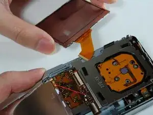
    • Use tweezers to flip open the connector holding the ribbon.

    • Gently pull out the LCD screen with the ribbon from the camera.

  10. KcsgQpe1BGICOaIv
    KcsgQpe1BGICOaIv
    pfNZAuldbE5VtbmF
    • Using a Phillips #00 screwdriver, remove the two screws on the side where the battery is located.

    • Remove the lanyard loop after the screws come off.

    • Slowly pull the side casing so it becomes dislocated from the top of the camera frame.

  11. WxVCW5FBfFZrMFOw
    WxVCW5FBfFZrMFOw
    xdSXDBxYXXSqdqKH
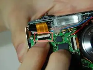
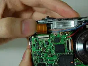
    • On the front of the camera, detach the ribbon from the connector.

  12. qTJFbANJKGk15tDL
    qTJFbANJKGk15tDL
    qKvE2SxuIeYre3LA
    RgWKeZFMmW5Q3jpC
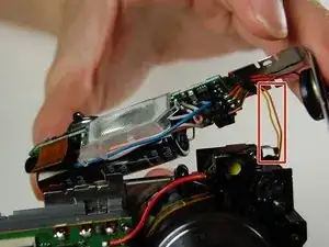
    • Carefully remove the L shaped frame from the camera.

    • There is a yellow and orange wire connected to camera. Be careful not to pull them off.

    • At the bottom of the camera, the L-shaped frame is connected by two plastic bumps and a metal tab.

  13. GFTF5preZo3Bk5dQ
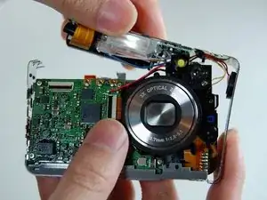
    • Using a Phillips #00 screwdriver, remove the two screws on the front of the flash assembly.

    • Remove flash assembly, and replace it with a new flash assembly.

Conclusion

To reassemble your device, follow these instructions in reverse order.
Christian

Member since: 28/01/11

320 Reputation

0 comments