Introduction

Please complete the dis-assembly guide before attempting to install new data ports, as it is a prerequisite.

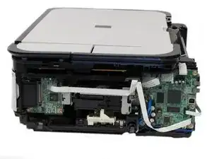
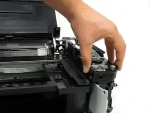
Use this guide to replace a broken data port to get your USB and card readers back.

  1. ofUToxLQNCZ2HO1M
    ofUToxLQNCZ2HO1M
    qMuoFBO3wZXf2Uak
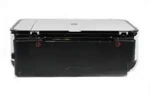
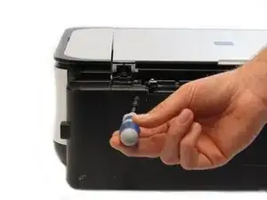
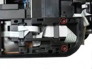
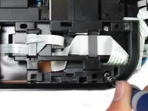
    • Remove the two 7.9 mm screws using a Phillips #1 screwdriver.

  2. b2BGODeXYFwttEkU
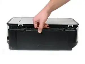
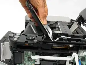
    • Lift up the back cover to remove it.

    • You may need to lift firmly as it requires quite a bit of force.

    "quite a bit of force" is almost an understatement, I found 2 clips along the bottom of that rear piece, one at the far left one around the middle (indicated by an arrow on the underside of the machine) - undoing these required much persistence with a screwdriver

    Perhaps Fuzz -

    Thank you, Perhaps Fuzz. Thank you.

    Marji Zintz -

  3. tI1uXZAEJ2npisIV
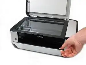
    • Open the front tray.

  4. mgPdKhjJ1FmS5Cw3
    mgPdKhjJ1FmS5Cw3
    vLH5mhugWcJC5E3H
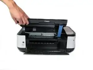
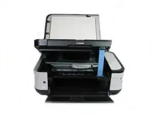
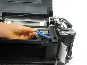
    • Open the scanner compartment.

    • Make sure the blue lever locks into place to keep the compartment open.

  5. QUiyjWRRDx2DYjAn
    QUiyjWRRDx2DYjAn
    PwaZVwcng324MBNk
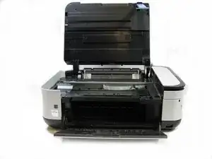
    • Remove the blue lever from its slot by pushing it back and twisting clockwise.

    • Close the scanner compartment and cover.

  6. ODKxhbUjCbwwC61m
    ODKxhbUjCbwwC61m
    VTTvnOP2ZsXoHL5C
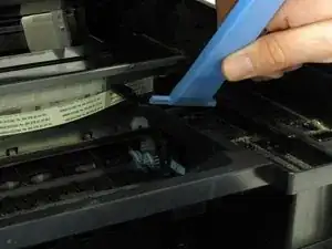
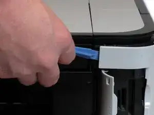
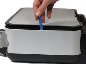
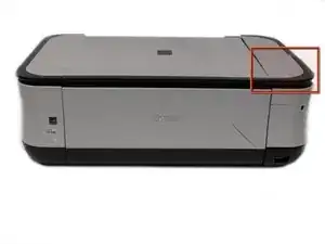
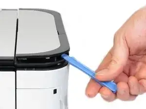
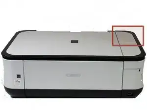
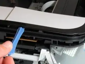
    • Pry open the side cover with the plastic opening tool.

  7. HJMrafeNBYxXWvMC
    HJMrafeNBYxXWvMC
    cZjooH63AqHQRFa2
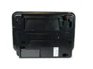
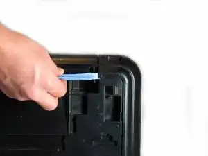
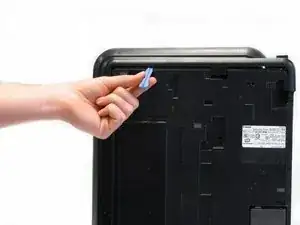
    • Flip the printer over so that you are facing the bottom of the printer.

    • Use the plastic opening tool to remove the corner of the side panel from the plastic pin.

  8. ydLX6TeDiv1QeF5F
    ydLX6TeDiv1QeF5F
    wRnOCOtihWZ6SEqH
    • Use the plastic opening tool to loosen the side panel from the bottom of the printer.

  9. O2rCJDoUxStVDfWA
    O2rCJDoUxStVDfWA
    mYgYRYyfiwIMiOJn
    • Using the plastic opening tool, pry off the top cover of the LCD assembly.

    • Pry around the front and side edges for the easiest removal.

  10. wNiOeipQKDTkXBQE
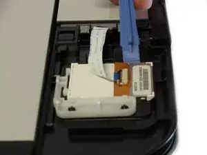
    • After removing the top cover of the LCD assembly, remove the LCD using the plastic opening tool.

  11. vxkZ2J3NxGjpwQNi
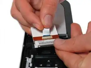
    • Completely remove the LCD by disconnecting the ribbon cable with a gentle pull.

  12. 3mmDxvln2bu2ifrT
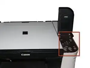
    • Locate the buttons on the printer.

  13. NgF2T6dfAMRSEhWZ
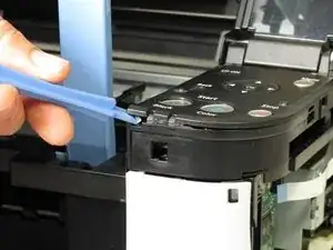
    • Using the plastic opening tool, gently pry around the button cover to remove it from its fixture.

  14. hYnKnVJBTKqnF2sG
    hYnKnVJBTKqnF2sG
    GdvOADBiPwHyYk6p
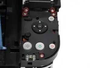
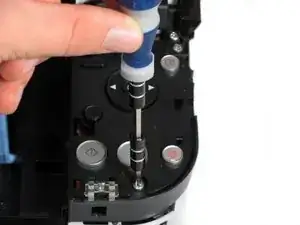
    • Remove the five 7.7 mm screws using a Phillips #1 screwdriver.

  15. cFSKUFwSOjyMTqXt
    cFSKUFwSOjyMTqXt
    NssiDCt2MYCGLmdH
    • Using the plastic opening tool, gently pry around the cover behind the LCD screen to remove it from its fixture.

  16. lVTCDKYa1hNMhrf6
    lVTCDKYa1hNMhrf6
    guRxlLFshoxZP1NZ
    • Remove the two 7.8 mm screws using a Phillips #1 screwdriver.

  17. oSDoNGq4cmFNESIQ
    • Gently pull the LCD screen up to remove it from its fixture.

  18. MKWRshtqq2ADwJjV
    • Use the plastic opening tool to pry off the plastic button assembly.

  19. oKHKSqxyScLWjbxM
    • Gently pull the plastic button assembly up to remove it.

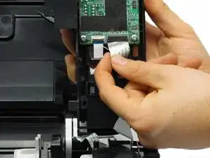
    • The plastic button assembly has a ribbon cable connected on the bottom, so make sure to be careful pulling it.

  20. IM4xleYS5BrlsZCS
    • Remove the ribbon cable connected to the backside of the plastic button assembly.

  21. EMU2WHcAPOwuOMeP
    EMU2WHcAPOwuOMeP
    PEpDM4NJOAtFbPnO
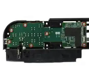
    • Remove the seven 8.7 mm screws using the Phillips #1 screwdriver.

  22. uYI1I5dJYK4oC15M
    uYI1I5dJYK4oC15M
    Kw1grHqqXZgiVMqK
    6jrMPYRRYKZX5p2H
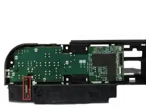
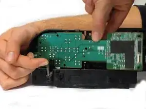
    • Locate the spring that holds the PCB in place on the bottom left of the plastic button assembly.

    • Gently lift the spring and pull the board out of its plastic button assembly.

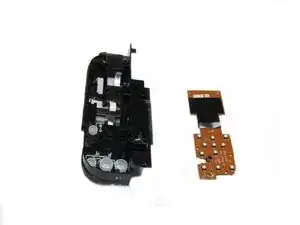
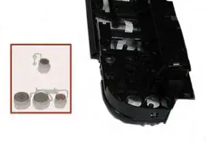
  23. BPW3Wv2LP4UNMPXM
    • Remove the buttons from the plastic button assembly.

  24. tXsgQBhdTVVuqGCl
    tXsgQBhdTVVuqGCl
    quYGE5YmEyuBZXVv
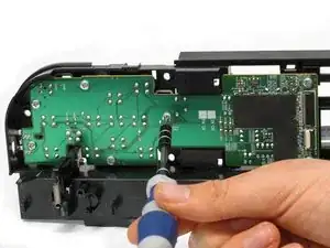
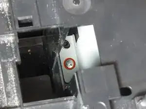
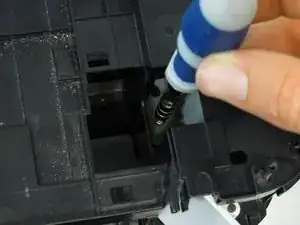
    • Remove the screw using the Phillips #1 screwdriver.

    • 7.5 mm Phillips #1 screw

  25. GQad3DaXwApl5nNV
    GQad3DaXwApl5nNV
    CgqY5uMPM3MtJhEE
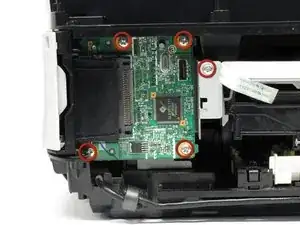
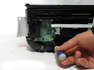
    • Remove the five screws using the Phillips #1 screwdriver.

    • Five 3.5 mm Phillips #1 screws

  26. YGQHaUDyNhJW1ruV
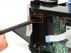
    • Remove the small plastic clip using the spudger.

    • Small plastic clip

  27. AKJRZUl1VXgOb1Mh
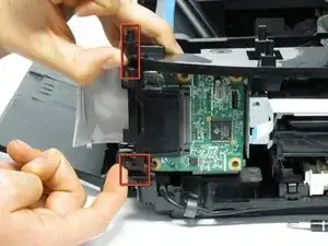
    • Pull plastic inserts out of the holes in the top and bottom.

    • Top and bottom plastic inserts

  28. sbgrTqoAPaKykbES
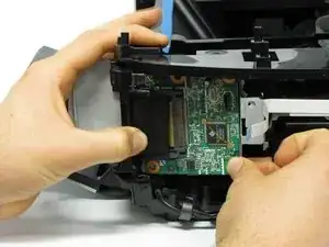
    • Completely remove the board from the printer by pulling the board towards the back of the printer.

    • This requires effort and time as the board comes out little by little.

Conclusion

To reassemble your device, follow these instructions in reverse order.
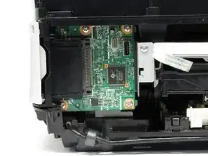
Steven MacLean

Member since: 15/01/13

86 Reputation

0 comments