Introduction
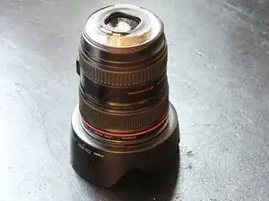
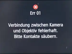
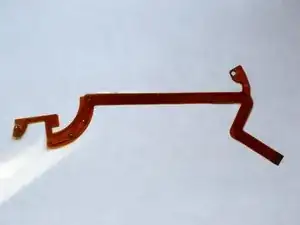
The camera shows Err01 every now and then - Connection between camera and lens faulty. Please clean the contacts. In most cases, a conductor path in the lens is broken.
Tools
-
-
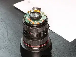
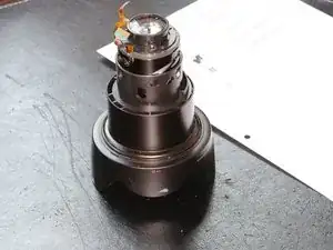
The bayonet lock is mounted with four little screws. Remove them and mark them (like all other screws) and put them aside
-
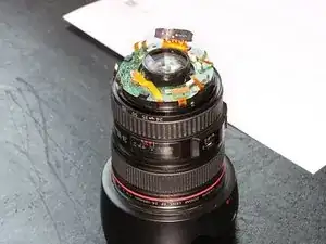
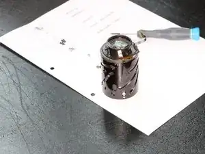
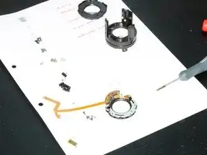
The black insert is a plastic part and fixed with four clips from below. The most upper ring can be lifted a little bit on the opposite side of the contacts. By doing that, you can remove one or two clips from below to push out the black insert carefully.
-
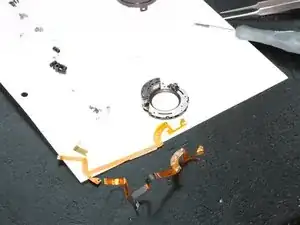
Be especially carefully not to put too much tension on the flex-cable which connects the contact-strip with the PCB below!
-
The contact-strip itself is fixed with two very tiny PH0-Phillips-screws from the outer side. Please remove both of them and put them aside
-
-
-
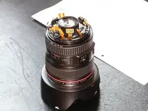
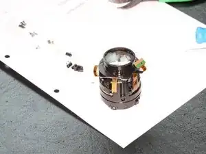
Now, remove all flex cables from the the PCB very carefully. There are several different ways of connections.
-
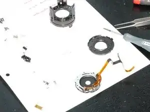
remove the screw which holds the PCB in place and remove the board afterwards
-
-
-
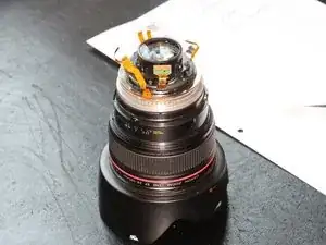
now, it gets a little bit tricky: the rails of the "cage" are guided by little pins. These are individually sized and have to go exactly where they were before. So be careful and document everything in detail
-
Um Ihr Gerät wieder zusammenzubauen, befolgen Sie diese Anweisungen in umgekehrter Reihenfolge.
2 comments
Stimmt nicht ganz. Die “Collars” mit dem Kreuz sind exzentrische und justieren die Optik. Einfach reinschrauben wo´s mal war is nicht! Danach kann man das Teil in die Tonne kloppen oder dann für teures Geld zu Canon schicken.
Bitte unbedingt alle Bastelwütigen genau auf das hinweisen.
Was kann man tun? In der Regel ist immer einer von den dreien zentrisch; der kann bedenkenlos am gleichen Platz montiert werden. Vom Rest von jeder Seite genug Fotos machen und Markierunen anbringen WO genau das Kreuz war. Da geht´s eigentlich um´s Hunderstel. Wenn´s danach für den Hausgebrauch bei f8 ist… Also Zeit lassen, Linsengruppen nicht verdrehen usw.
Jupp, da muss auf jeden Fall drauf hingewiesen werden. Wenn die exzentrischen Pins vorne an der Blenden/IS Einheit beim rauspulen auch noch verbogen werden, wars das ohnehin. So, wie in der Anleitung beschrieben, ist das leider eine Reparatur für die Tonne.
Patch -
