Introduction
In this installation guide, you will remove a damaged display screen and install a new one in your Blackberry 8700c. The pictures above each step correspond to that step. If you hover your mouse over a picture, a larger picture will appear on the left. Each step's corresponding pictures are referred to as Pictures 1, 2, or 3. Picture 1 is the far-left picture, Picture 2 is the middle picture, and Picture 3 is the far-right picture.
Tools
-
-
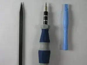
The required tools are pictured on the left (Picture 1). The tools are, left to right, spudger, T6 screwdriver, plastic opening tool.
-
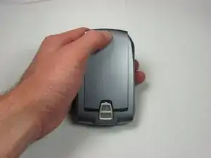
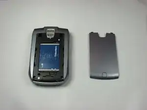
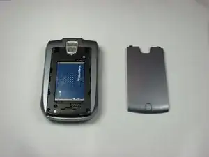
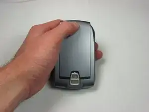
Remove the back cover by pushing the button near the bottom of the phone (Picture 2) and sliding the cover off (Picture 3).
-
-
-
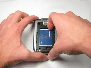
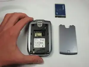
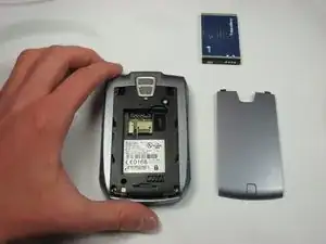
Using your fingernail, remove the battery by pulling on the notch on the top-right of the battery.
-
-
-
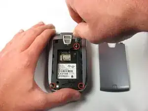
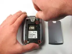
Remove the inner back cover by unscrewing all three T6 screws (circled in Picture 1) with a T6 Torx screwdriver.
-
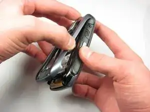
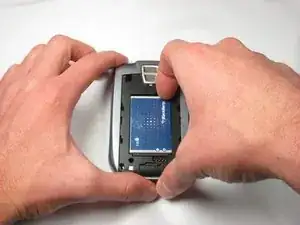
Pull the inner back cover from the bottom towards you and up (Picture 2).
-
-
-
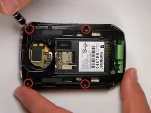
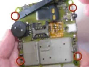
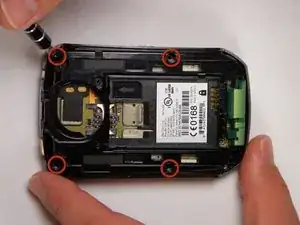
Remove the inner cover by unscrewing all four T6 screws with a T6 Torx screwdriver (circled in Picture 1).
-
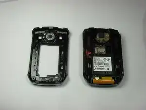
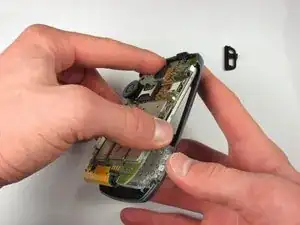
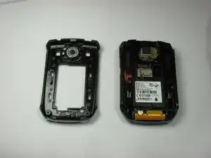
Lift the inner cover off the phone.
-
-
-
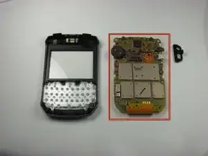
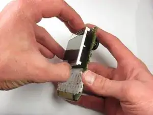
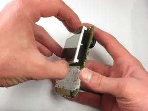
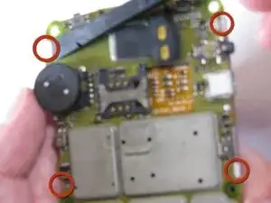
Detach the display screen from the logic board by using a spudger to unclip the four clips holding the display screen (circled in Picture 1). Gently pull the display screen away from the logic board so that none of the clips are engaged.
-
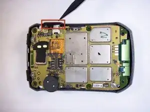
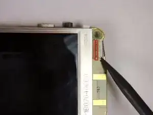
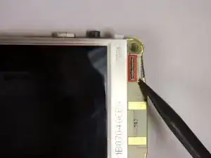
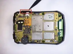
The display screen is attached to the logic board by a metal ribbon. Remove the display screen by disengaging the ribbon lock. Use a spudger to push the thin black bar down (circled in Picture 2). Gently pull the display screen and ribbon out of the logic board.
-
-
-
Install the new display screen by reattaching it to the logic board. Reinsert the ribbon into the cable lock. Use the spudger to push the thin black bar up (circled in Picture 1).
-
Gently place the display screen against the logic board so that it is aligned with the clips. Use a spudger to engage all four clips (circled in Picture 3).
-
-
-
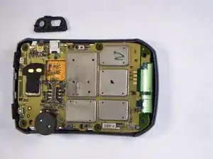
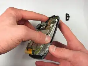
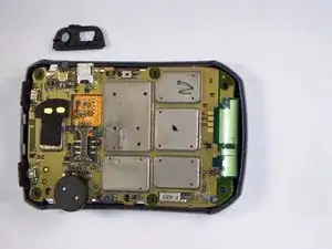
Position the small black piece that fell out in Step 2 against the headphone jack on the side of the phone (circled in Picture 2).
-
Replace the inner cover on the phone by screwing in all four T6 screws (circled in Picture 3) with a T6 Torx screwdriver.
-
-
-
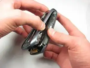
Replace the inner back cover by snapping the top of the cover against the phone. Push down on the bottom of the inner back cover to snap the entire cover into place.
-
Screw in all four T6 screws (circled in Picture 3) with a T6 Torx screwdriver.
-
-
-
Replace the battery by positioning the top of the battery in the phone and snapping in the bottom.
-
