Introduction
This guide will show how to disassemble the Black and Decker CHV1510 cordless, handheld vacuum to remove and replace a faulty power switch. It is a fairly simple process that requires only a plastic pry tool and a Phillips head screwdriver. This specific handheld vacuum is a discontinued product, making it extremely difficult to find any sufficient guides to aid consumers in fixing components of the product. Other concerns from consumers mostly focus on issues with the battery, motor failure, or power switch concerns.
The components in this device are extremely intertwined, meaning you may think your vacuum might have a motor issue when the power switch assembly is the real problem not supplying the motor with power. This is crucial, in that it is important to inspect your device thoroughly to ensure you are diagnosing the correct component to be replaced.
This guide will provide accessibility in helping others fix their previously unusable devices in the hopes of not having to purchase a new or different handheld vacuum. Of course handheld vacuums are very simple, though many consumers may not explore the options to fix their device, on the quick assumption that it may be most time effective to go purchase another inexpensive substituted product.
-
-
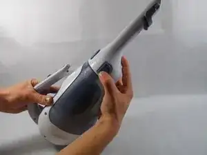
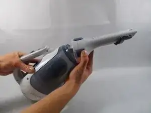
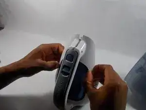
Remove nozzle by pressing two blue buttons with unlock symbols on the side of the nozzle.
-
Pull the nozzle upward.
-
-
-
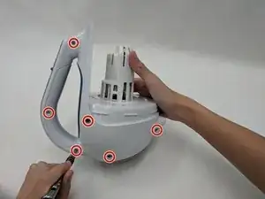
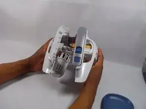
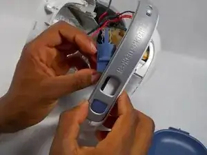
Remove the six exterior 2 mm Phillips #1 screws that secure the two halves of the outer shell.
-
-
-
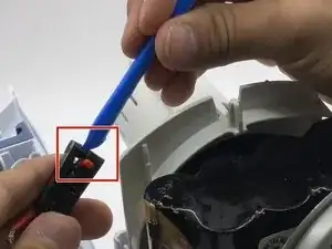
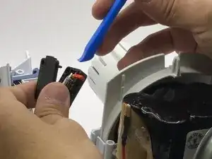
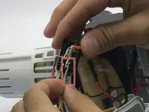
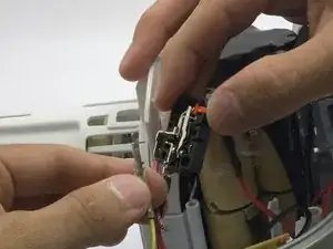
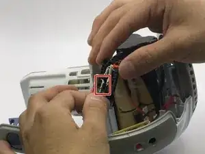
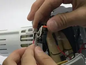
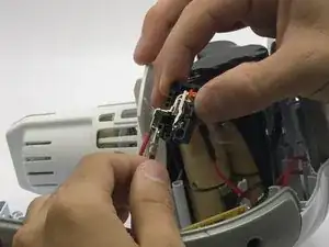
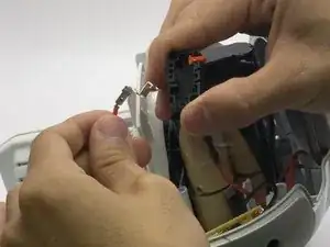
Gently pull the red wire with the black wire casing in the middle out of the assembly for removal.
-
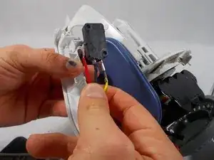
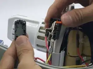
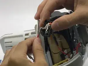
To reassemble this device, follow these instructions in reverse order. Make sure you keep track of which wire belongs to which flat metal assembly tab, to ensure each wire is grounded so power is connected properly.