Introduction

This is a prerequisite-only guide! This guide is part of another procedure and is not meant to be used alone.

  1. YRHZAQDYqujjXMY5
    YRHZAQDYqujjXMY5
    KLCX6awLsUbZnFYG
    BSHBhtIsZbfpvQAZ
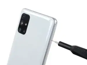
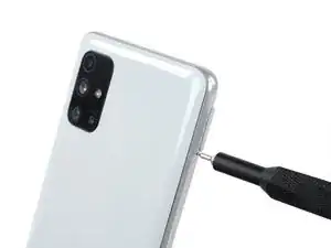
    • Insert a SIM eject tool into the small hole on the SIM card tray on the left edge of the phone.

    • Press firmly to eject the tray.

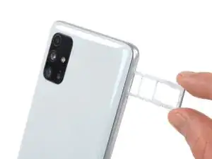
    • Remove the SIM card tray.

    • When reinserting the cards, make sure to properly orient them in the tray.

  2. rukyhPf2HeLEPWYD
    • Before beginning this procedure, completely power off your phone.

    • Prepare an iOpener and apply it to the back cover for at least two minutes.

    • A hair dryer, heat gun, or hot plate may also be used, but be careful not to overheat the phone—the display and internal battery are both susceptible to heat damage.

  3. 1AwPydyiLVRm1tbm
    1AwPydyiLVRm1tbm
    EqecmVYxpVmJlJ3G
    5st11vWsWN23x5TN
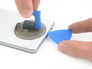
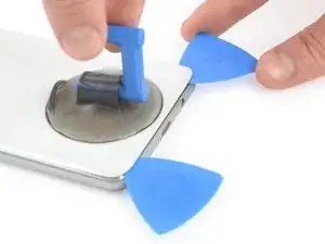
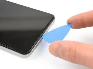
    • Apply a suction handle to the back cover, as close to the USB-C port as possible.

    • Lift the back cover's bottom edge with your suction handle, opening a slight gap between the back cover and the frame.

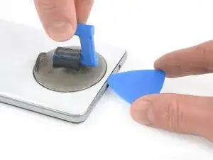
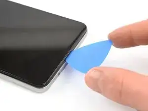
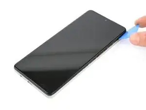
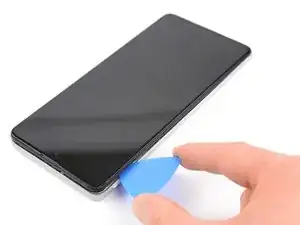
    • Insert the tip of an opening pick in the gap you created.

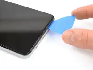
    • Slide the opening pick to the bottom left corner and leave it there.

  4. EM1KPLM6wrS266NE
    EM1KPLM6wrS266NE
    JLXsTbTHmQb2F4GG
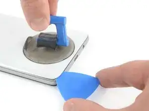
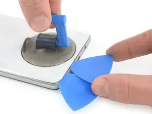
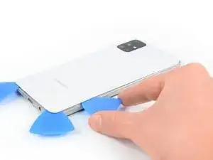
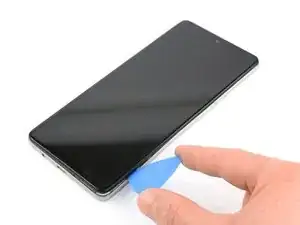
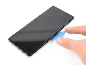
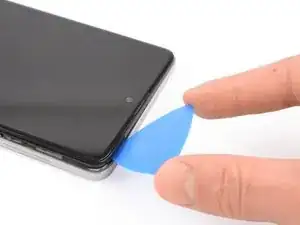
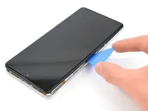
    • Insert a second opening pick and slide it from the bottom left corner to the bottom right corner to cut the adhesive.

    • Leave the opening picks in place to prevent the adhesive from resealing.

  5. lqWFoPYNlJNmGGOI
    lqWFoPYNlJNmGGOI
    WDNl4vCfGnAvuYkL
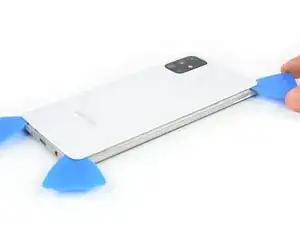
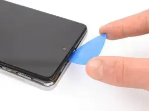
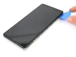
    • Insert a third opening pick under the bottom right corner of the back cover.

    • If you have any trouble, apply more heat to further soften the adhesive. Follow the iOpener instructions to avoid overheating.

    • Slide it along the right edge of the phone to the top right corner to cut the adhesive.

    • Leave the opening pick in the top right corner to prevent the adhesive from resealing.

  6. CqH3BZ2KEWUeXv5Z
    CqH3BZ2KEWUeXv5Z
    qcrFRvT5dtuSUYAx
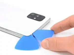
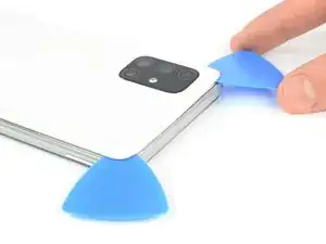
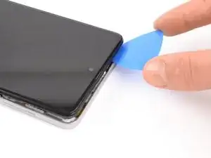
    • Insert a fourth opening pick under the top right corner.

    • Slide it along the top edge to the left corner to cut the adhesive.

    • Leave the opening pick in its place to prevent the adhesive from resealing.

  7. SF35E6kpxyBNIlhN
    SF35E6kpxyBNIlhN
    vRR3sMgMVJUUXjOg
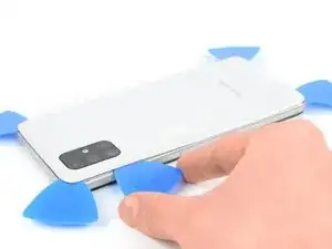
    • Insert a fifth opening pick on the top left corner and slide it along the edge to cut the remaining adhesive.

  8. pQLEOf2U3bSfYpXC
    • Remove the back cover.

  9. rHA5voNVZtNkXNWR
    rHA5voNVZtNkXNWR
    mWJmkTGEVZEAKoYG
    • Use the pointy end of a spudger to disconnect the fingerprint sensor from the motherboard.

  10. 5DPtIxYMqwFfCSpM
    • Remove the 15 4.0 mm-long Phillips #00 screws securing the midframe.

  11. jnqiMqcVIKtIlDiv
    jnqiMqcVIKtIlDiv
    IBmFYoyFVX6y3ZQG
    E6qI4sQIZnD2f1Px
    • The midframe is held by plastic clips.

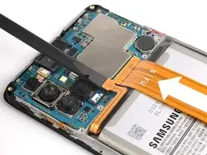
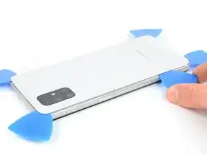
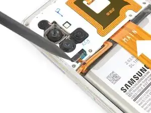
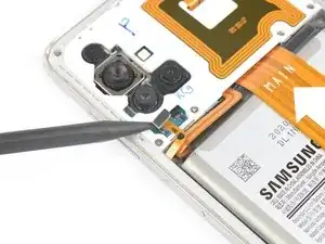
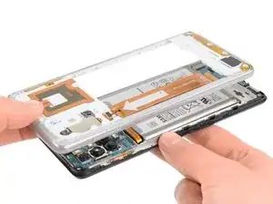
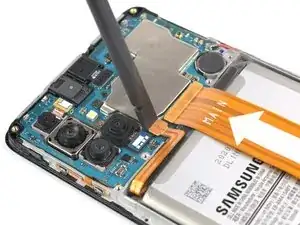
    • Insert an opening pick between midframe and display near the usb-c port.

    • Slide the opening pick to bottom right corner to release the plastic clips.

  12. QyWZeQKLSkYdllFi
    QyWZeQKLSkYdllFi
    ROdIfFODrTM6BMOD
    YUF3MvLOLXq5x6kX
    • Slide the opening pick along the right edge to release the plastic clips.

  13. ECpaAMhwhIE3j1Qe
    ECpaAMhwhIE3j1Qe
    Em2OOYVBukILNsdR
    reHeFAsxIL6LJ3DJ
    • Slide the opening pick along the top edge to release the midframe from the plastic clips.

  14. spKvZEUDUCeOJXCM
    spKvZEUDUCeOJXCM
    AbNSImiX5p6rVXKE
    AkeYKXGo5Hmw2CRV
    • Slide the opening pick along the left edge to release the plastic clips.

  15. ht4iafUICMI6JrPA
    • Remove the midframe.

  16. dXCpwJ6sqSoGJHNb
    dXCpwJ6sqSoGJHNb
    x2NZhNh6qDoJEXly
    • Use the flat end of a spudger to disconnect the battery.

Conclusion

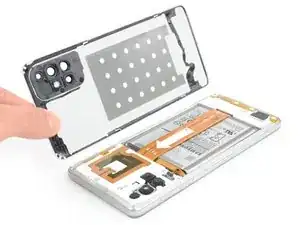
To reassemble your device, follow these instructions in reverse order.

Adriana Zwink

Member since: 18/12/19

47683 Reputation

0 comments