Introduction

This is a prerequisite-only guide! This guide is part of another procedure and is not meant to be used alone.

  1. KrdjGIhaDutm4BLD
    KrdjGIhaDutm4BLD
    rqRXkXVFYNGuMqfN
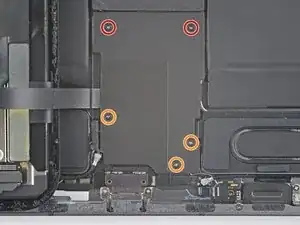
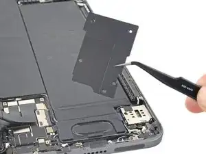
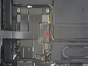
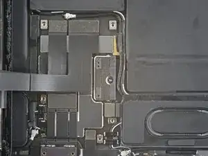
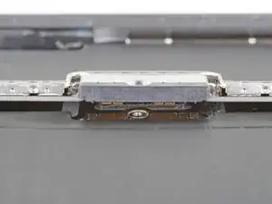
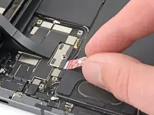
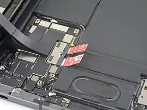
    • Use a Phillips screwdriver to remove the five screws securing the lower cable shield to the logic board:

    • Two 2.0 mm screws

    • Three 1.3 mm screws

  2. ayiAkOBcA4M3MQZO
    • Use tweezers or your fingers to grab and remove the lower cable shield.

  3. UwfpTYKfOAnwqQAB
    UwfpTYKfOAnwqQAB
    huDrXWDACcMgCPul
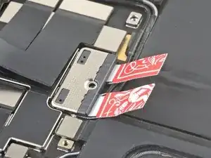
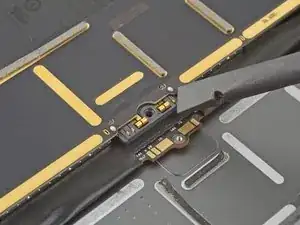
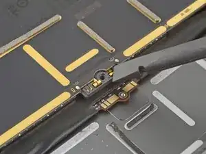
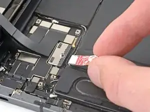
    • Use a Phillips screwdriver to remove the 1.8 mm screw securing the battery connector to the logic board.

  4. wIiYmwpPKiiWBiTd
    wIiYmwpPKiiWBiTd
    NXmwhiFO4bEu2OqI
    OPWiBSyhgUEQWphn
    • These photos show what the battery connector looks like underneath the logic board. Use these photos as a reference while you safely disconnect the battery.

    • Notice that the battery connector has cantilever springs on the logic board that press against the battery contact pads. Since both the logic board and battery are glued down, you'll need to slide something thin and flexible between the contact points to disconnect the battery.

  5. JsPsrZl5TyW2BOOQ
    JsPsrZl5TyW2BOOQ
    tBPo2sCL5r6YLdSA
    CAeXYc2bSyv2peRI
    • Cut two 6 mm wide strips from a playing card or cardstock to use as a battery blocker.

    • The strips should be about 4 cm long so you can easily grip them.

  6. XRyRVLDJXCLMhVmK
    XRyRVLDJXCLMhVmK
    dFDejwOPRcAuPXF3
    XeZ2qFlXwlBZHu66
    • Insert the card strips on each side of the battery connector until they stop.

Conclusion

To reassemble your device, follow these instructions in reverse order.

Chayton Ritter

Member since: 21/08/20

17428 Reputation

0 comments