Introduction

This guide shows how to remove and replace the wheel drive motor on the Barreto Tiller E1320 2016.

  1. s2YGUE2hAZBeY2af
    s2YGUE2hAZBeY2af
    ZZcXNQfl6oHSSvcK
    • Before you begin, ensure that the engine is powered down and cool to the touch.

    • Grab the plastic housing at the end of the spark plug wire and pull firmly to disconnect it.

  2. 5XNxZUOMumNRQnZi
    5XNxZUOMumNRQnZi
    PRbKxuQaVOccHEaH
    • Flip the red engine ON/OFF switch to the OFF position.

  3. ELbXP1OZsK5dtsBV
    ELbXP1OZsK5dtsBV
    RrbPTfJWnGLicru3
    • Flip the fuel valve lever to the OFF position.

  4. jOQUT6h4DWhEndhK
    jOQUT6h4DWhEndhK
    pwrPhQvk2RKy5MpD
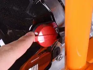
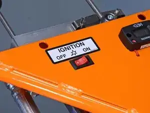
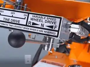
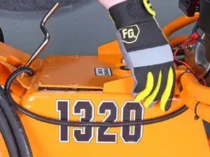
    • Flip the ignition switch to the OFF position.

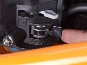
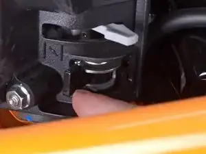
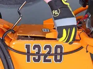
    • Ensure the wheel drive control lever is set to the neutral position.

  5. BCLCetXmDSNeQdgl
    BCLCetXmDSNeQdgl
    UJvQ5wEOPFLWwH1F
    TU2RsedTJJWJDUBA
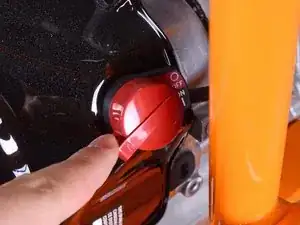
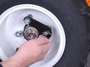
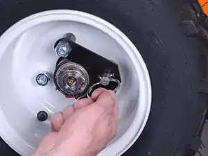
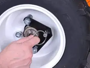
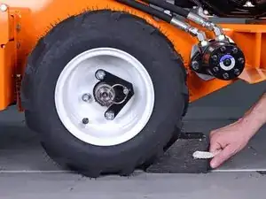
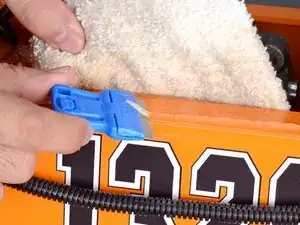
    • Pull the locking pin out and rotate it 90˚ to unlock the right wheel from the hub.

    • Repeat for the left wheel.

  6. iljfxDVpMMRf1PiE
    • Insert wheel chocks underneath each wheel to keep the device stationary during disassembly.

  7. hJZAFeNEhXxG3uIA
    • Use a 14 mm hex key to remove the tank fill plug.

  8. 1QcHCaYoK3rihouQ
    • Use a siphon to pump out as much fluid as you're able to, totaling about 14 gallons.

  9. OrpeHJEXjRjuyUSF
    OrpeHJEXjRjuyUSF
    LosrCGKwbagGXT2D
    ThuYylZXhqBuvyYr
    • Remove the end of the tank breather tube from inside the engine guard structural pipe.

  10. XDhjXo3RaPtJHdaG
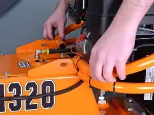
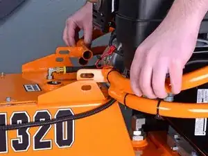
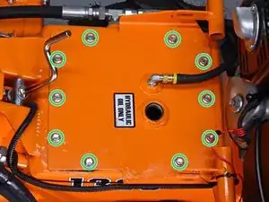
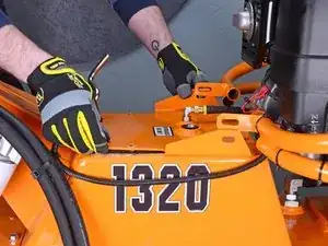
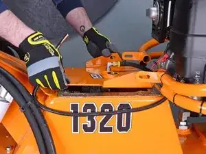
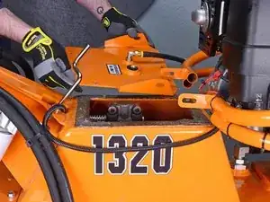
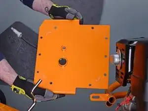
    • Use a 9/16 inch socket and wrench to remove the two bolts and accompanying nuts securing the engine guard to the tank lid, one on each side.

  11. Au5UOK6XXmFkiPVe
    Au5UOK6XXmFkiPVe
    oW2vbRLDD53Spb6Y
    • Lift the engine guard up above the tank lid flanges.

  12. OSClZ3ZKmPKkQPMw
    • Use a 3/8 inch socket to remove the ten bolts securing the tank lid.

  13. FtXAImxTBRacqP4C
    FtXAImxTBRacqP4C
    BRGbkEZMTskGGYaj
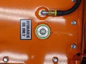
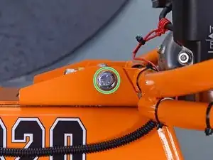
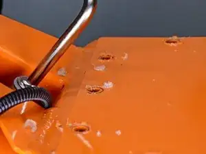
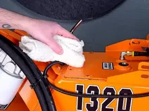
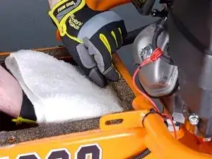
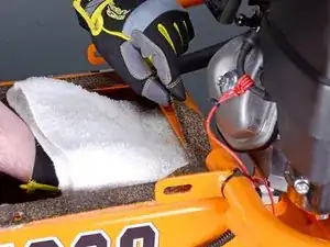
    • Use a shop towel to clean and remove any remnants of silicone gasket material from the top of the lid and surrounding areas.

    • Try to prevent any silicone remnants from falling into the hydraulic fluid tank.

  14. kPFYBR1KfMGmrjqH
    kPFYBR1KfMGmrjqH
    2Q4Yaw2vjOhVdeT5
    • Lift up on the lid to break the seal around the perimeter of the gasket.

  15. cIR4gTtTU623aVPb
    cIR4gTtTU623aVPb
    WBm2oF3VD3VcKDWT
    TL26l3w1cYymKkN4
    • Lift the tank lid out and around the engine guard mounting tabs to remove it.

  16. 5N4wW3LHoTjxEgXX
    5N4wW3LHoTjxEgXX
    kAtOKbxAuGYsWhVn
    3a4YNJmqN2kZPcXD
    • When peeling up the gasket, hold a shop towel underneath the lip of the tank to prevent any silicone remnants from falling in.

    • Peel the gasket up from around the perimeter of the tank.

    • Remove the gasket.

  17. ubKwMSddGmPmR2Uo
    ubKwMSddGmPmR2Uo
    2DH4FKDlCErNwjlH
    • Before reinstallation, remove all remnants of old silicone gasket from both the rim of the fluid tank as well as the tank's lid.

  18. oEmBE2oH5qQToa5J
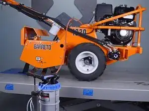
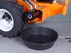
    • Place an oil drain pan underneath the wheel drive motor to catch hydraulic fluid that will spill out during this procedure.

  19. Y4KVtZyMjbnq4ZG2
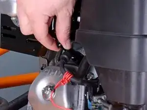
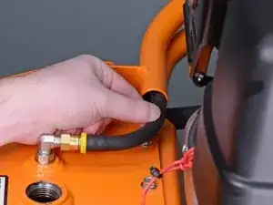
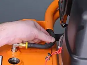
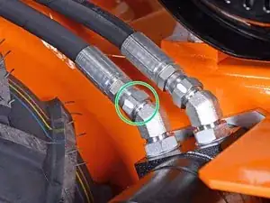
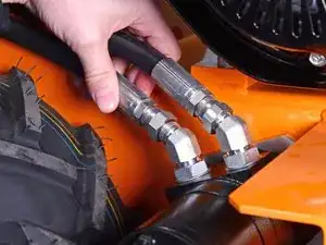
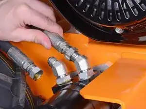
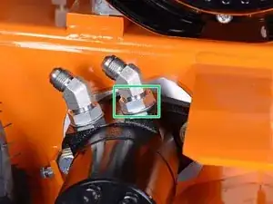
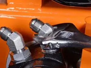
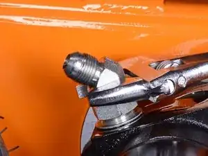
    • Use an adjustable wrench to loosen the nut securing the lower fluid hose to the fitting on the wheel motor.

  20. B2lthnFvmVBMfL4j
    B2lthnFvmVBMfL4j
    q4Dn2kMI2KM2IUZG
    j4CVHgy2VbcD6GQE
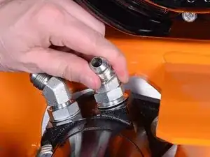
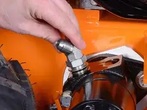
    • Remove the lower fluid hose from the wheel motor.

    • Allow residual fluid in the hose to drip into the drain pan underneath the motor.

  21. WQFxnFNnYtXtaVqp
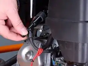
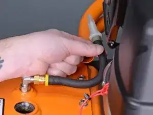
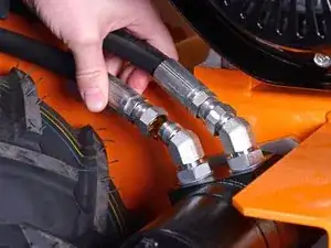
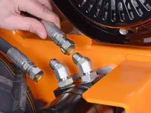
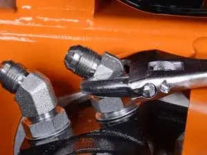
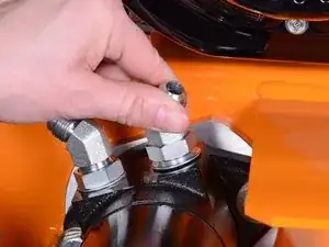
    • Use an adjustable wrench to loosen the nut securing the upper fluid hose to the fitting on the wheel motor.

  22. EnvP1INHcJetJZW2
    EnvP1INHcJetJZW2
    yYeqELSwVOJHNOCa
    4XYCCJqT2GmIUNDc
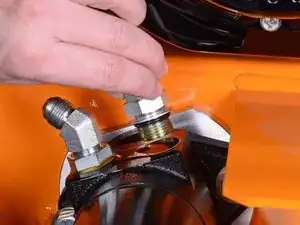
    • Remove the upper fluid hose from the wheel motor.

    • Allow residual fluid in the hose to drip into the drain pan underneath the motor.

  23. SKYyYOKuaKFMXGgs
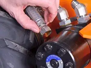
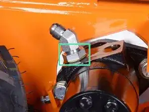
    • Place paper towels into the hose openings to block residual fluid from dripping as you continue the procedure.

  24. kdlTfvQqfZ4BLVxb
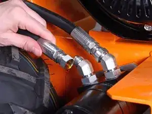
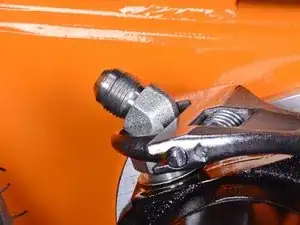
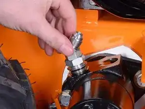
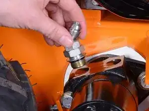
    • Use an adjustable wrench to loosen the nut locking the upper hose fitting to the wheel motor.

  25. mJcPc3PCNiqkydoy
    mJcPc3PCNiqkydoy
    acNGgcIIvIV4YE4o
    • Use an adjustable wrench on the fitting body to unthread it from the wheel motor.

  26. mSBa5DkRXKxchng4
    mSBa5DkRXKxchng4
    PZekIfMqFSSsHPKT
    rfchO6J1BGkCUtjt
    • Remove the upper fitting.

  27. HELIFUk4HTDiAFkw
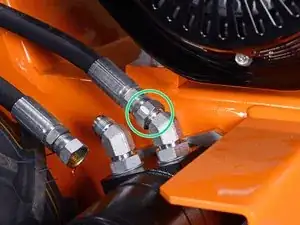
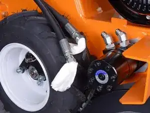
    • Use an adjustable wrench to loosen the nut locking the lower hose fitting to the wheel motor.

  28. IY2VFCxA2GGyNS1r
    IY2VFCxA2GGyNS1r
    hfYveSjWTYBCrA6o
    • Use an adjustable wrench on the fitting body to unthread it from the wheel motor.

  29. XcDckSWBMThNepLV
    XcDckSWBMThNepLV
    SPYHeuF5KrOEARGf
    mg1JYoLTmHMW2YSq
    • Remove the lower fitting.

  30. jXRYcEUXNPGNdCSQ
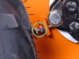
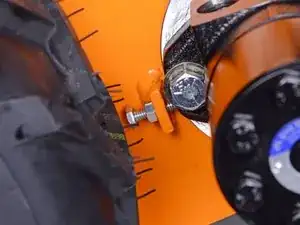
    • Use a 7/16 inch wrench to loosen the tensioner bolt's lock nut.

    • Back the tensioner bolt out about 1/2 inch.

    • Don't fully remove the tensioner bolt.

  31. AZvYrXYPRFQUWVKn
    AZvYrXYPRFQUWVKn
    s5YKOZqyDhFRYgAK
    rcP1CUe36UHiR6YY
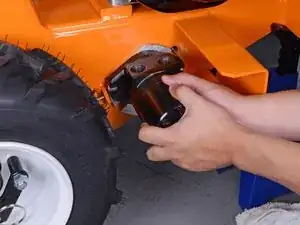
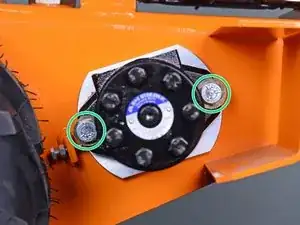
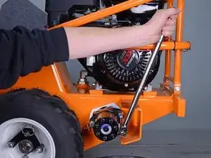
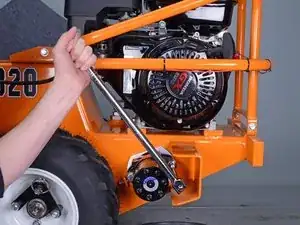
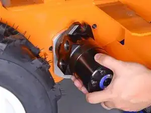
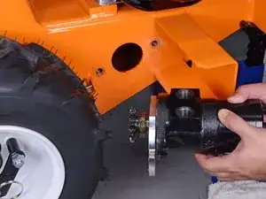
    • Use a 3/4 inch socket and breaker bar to remove the two bolts securing the wheel drive motor to the frame.

  32. 6Q25WZ3yiDjgDJSu
    6Q25WZ3yiDjgDJSu
    6EQirRctOSWUDFSa
    ANenhelhAgUeeWKg
    • During reinstallation, tighten the tensioner bolt down onto the motor housing to help align the motor with the spacer.

    • Tighten down both motor mounting bolts until there is no gap between the spacer and the frame or between the motor and the spacer.

    • Ensure the motor is aligned with the spacer before tightening.

  33. JlDc5rEOyfb5bPAV
    JlDc5rEOyfb5bPAV
    RpP1NU1mOC5c4dxC
    PhqPcXRaFp22rihW
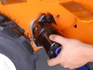
    • With the motor loose, rotate it 90˚ counterclockwise and push it as far left as it will go to give the drive chain some slack.

  34. I2aUsNBmMJGWEgM3
    I2aUsNBmMJGWEgM3
    GigxaxSfcI1dQWiy
    oWWkqC2ZNYZKSQN4
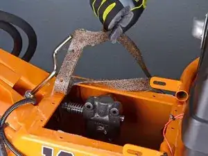
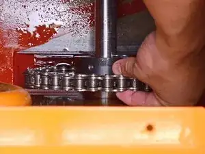
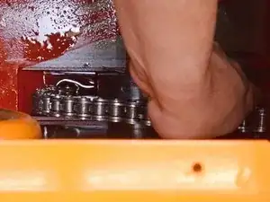
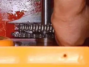
    • Reaching in from the top of the tank, lift the drive chain up and off of the axle gear.

    • If necessary, have another person hold the motor against the left side of the housing while the chain is being removed.

    • Remove the chain from the wheel drive motor sprocket.

  35. VfvpwKYZ53eZTRqA
    VfvpwKYZ53eZTRqA
    vGBDqRU6RUECIkNb
    • Remove the wheel drive motor, spacer, and sprocket assembly.

  36. FEKNLfZWW5cRttki
    FEKNLfZWW5cRttki
    EoxJLDOHJWiGDE4O
    • Remove the wheel motor spacer.

  37. 2IF3Cysp5WetHD4v
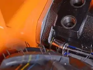
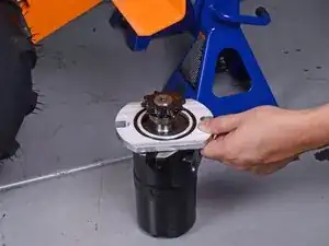
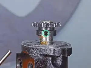
    • Use a 5/32 inch hex key to loosen the set screw securing the sprocket to the wheel motor shaft.

  38. VGZTvhOLBChplojs
    VGZTvhOLBChplojs
    ISLSUjwxU361K52h
    vbEWWJPOf5dMwnZT
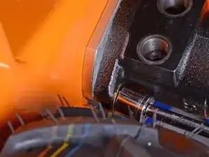
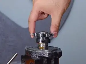
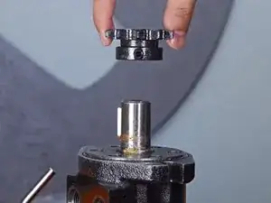
    • Remove the sprocket from the wheel motor shaft.

    • Reinstallation tip:

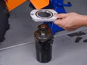
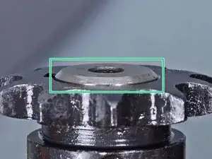
    • Align the top face of the sprocket with the end of the shaft's chamfer.

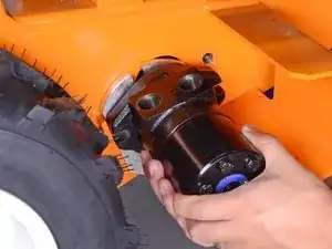
    • Only the motor remains.

Conclusion

To reassemble your device, follow these instructions in reverse order.

Carsten Frauenheim

Member since: 10/03/20

110978 Reputation

One comment

When putting back together I found it helpful to put the chain on the motor sprocket first. Then partially on the wheel drive sprocket and roll the unit

ARIEL -