Introduction

This guide shows how to remove and replace the actuator valve on the Barreto Tiller E1320 2016.

  1. s2YGUE2hAZBeY2af
    s2YGUE2hAZBeY2af
    ZZcXNQfl6oHSSvcK
    • Before you begin, ensure that the engine is powered down and cool to the touch.

    • Grab the plastic housing at the end of the spark plug wire and pull firmly to disconnect it.

  2. 5XNxZUOMumNRQnZi
    5XNxZUOMumNRQnZi
    PRbKxuQaVOccHEaH
    • Flip the red engine ON/OFF switch to the OFF position.

  3. ELbXP1OZsK5dtsBV
    ELbXP1OZsK5dtsBV
    RrbPTfJWnGLicru3
    • Flip the fuel valve lever to the OFF position.

  4. jOQUT6h4DWhEndhK
    jOQUT6h4DWhEndhK
    pwrPhQvk2RKy5MpD
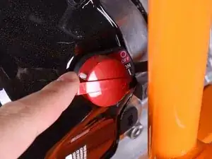
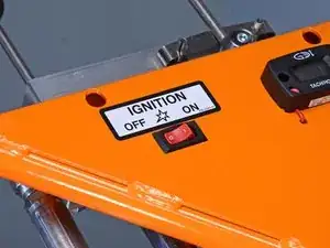
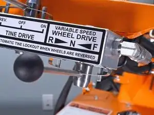
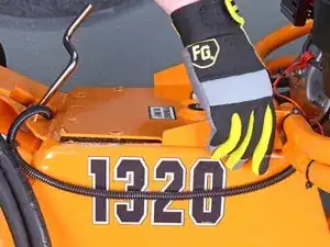
    • Flip the ignition switch to the OFF position.

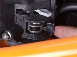
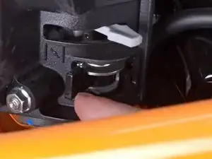
    • Ensure the wheel drive control lever is set to the neutral position.

  5. BCLCetXmDSNeQdgl
    BCLCetXmDSNeQdgl
    UJvQ5wEOPFLWwH1F
    TU2RsedTJJWJDUBA
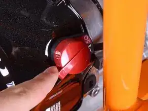
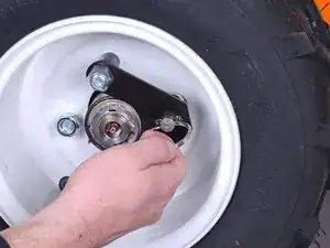
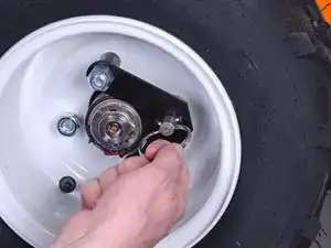
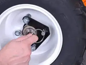
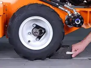
    • Pull the locking pin out and rotate it 90˚ to unlock the right wheel from the hub.

    • Repeat for the left wheel.

  6. iljfxDVpMMRf1PiE
    • Insert wheel chocks underneath each wheel to keep the device stationary during disassembly.

  7. hJZAFeNEhXxG3uIA
    • Use a 14 mm hex key to remove the tank fill plug.

  8. 1QcHCaYoK3rihouQ
    • Use a siphon to pump out as much fluid as you're able to, totaling about 14 gallons.

  9. OrpeHJEXjRjuyUSF
    OrpeHJEXjRjuyUSF
    LosrCGKwbagGXT2D
    ThuYylZXhqBuvyYr
    • Remove the end of the tank breather tube from inside the engine guard structural pipe.

  10. XDhjXo3RaPtJHdaG
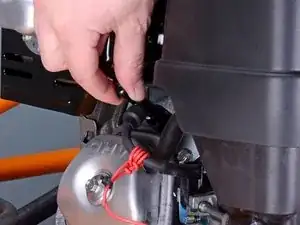
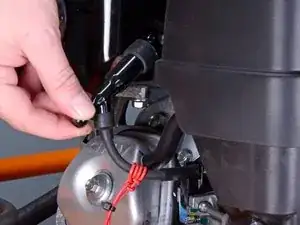
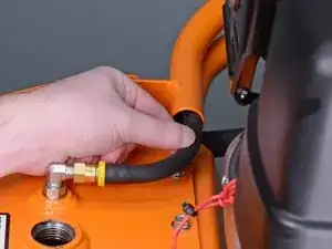
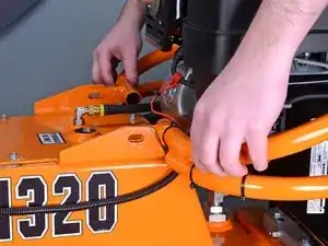
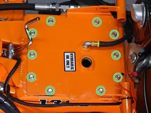
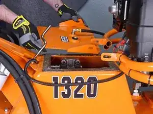
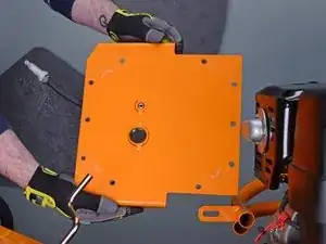
    • Use a 9/16 inch socket and wrench to remove the two bolts and accompanying nuts securing the engine guard to the tank lid, one on each side.

  11. Au5UOK6XXmFkiPVe
    Au5UOK6XXmFkiPVe
    oW2vbRLDD53Spb6Y
    • Lift the engine guard up above the tank lid flanges.

  12. OSClZ3ZKmPKkQPMw
    • Use a 3/8 inch socket to remove the ten bolts securing the tank lid.

  13. FtXAImxTBRacqP4C
    FtXAImxTBRacqP4C
    BRGbkEZMTskGGYaj
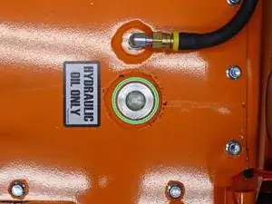
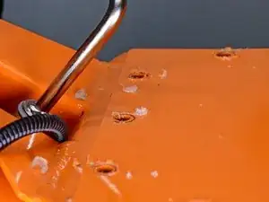
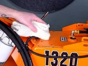
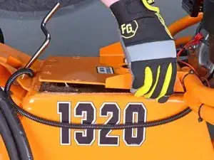
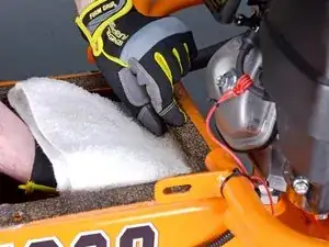
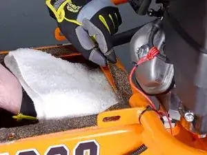
    • Use a shop towel to clean and remove any remnants of silicone gasket material from the top of the lid and surrounding areas.

    • Try to prevent any silicone remnants from falling into the hydraulic fluid tank.

  14. kPFYBR1KfMGmrjqH
    kPFYBR1KfMGmrjqH
    2Q4Yaw2vjOhVdeT5
    • Lift up on the lid to break the seal around the perimeter of the gasket.

  15. cIR4gTtTU623aVPb
    cIR4gTtTU623aVPb
    WBm2oF3VD3VcKDWT
    TL26l3w1cYymKkN4
    • Lift the tank lid out and around the engine guard mounting tabs to remove it.

  16. 5N4wW3LHoTjxEgXX
    5N4wW3LHoTjxEgXX
    kAtOKbxAuGYsWhVn
    3a4YNJmqN2kZPcXD
    • When peeling up the gasket, hold a shop towel underneath the lip of the tank to prevent any silicone remnants from falling in.

    • Peel the gasket up from around the perimeter of the tank.

    • Remove the gasket.

  17. ubKwMSddGmPmR2Uo
    ubKwMSddGmPmR2Uo
    2DH4FKDlCErNwjlH
    • Before reinstallation, remove all remnants of old silicone gasket from both the rim of the fluid tank as well as the tank's lid.

  18. 5mEW1ObioIirr2t6
    5mEW1ObioIirr2t6
    QQNRHM1VLEPcXuJ1
    RoqL4p3HJW4MrCOM
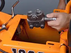
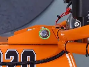
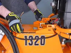
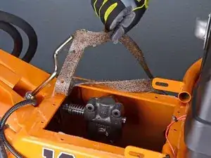
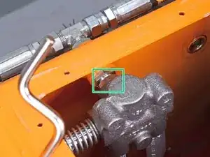
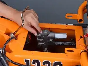
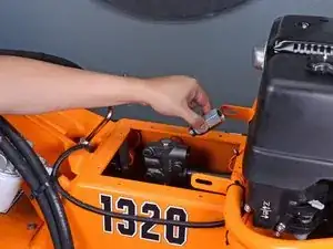
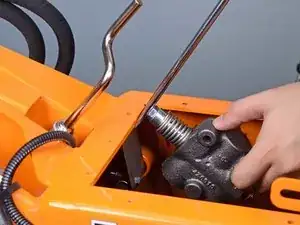
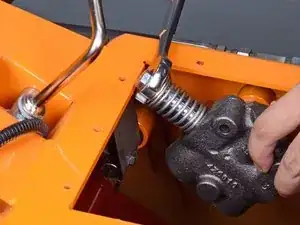
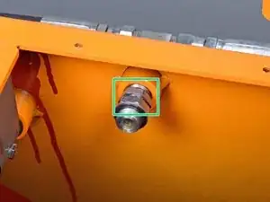
    • Use a 7/8 inch open-ended wrench or an adjustable wrench to loosen the lock nut closest to the valve on the actuator fitting.

  19. 6DLmqLj2LxyiHWrD
    6DLmqLj2LxyiHWrD
    DihNCQvCREepmTBM
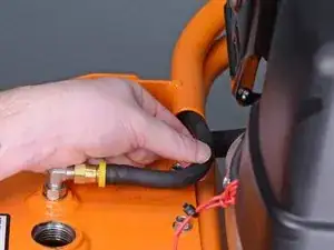
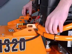
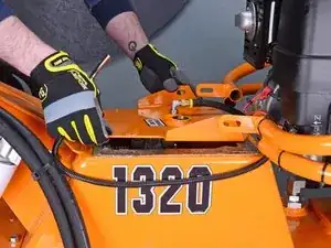
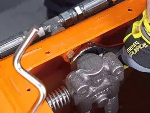
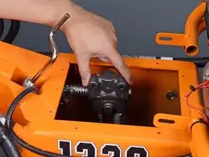
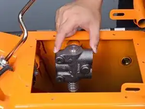
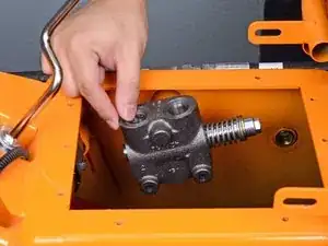
    • Rotate the actuator valve so the return tube and relief valve are horizontal and parallel to the tank opening, facing the engine.

  20. lHkTGRWhQaaCXZib
    lHkTGRWhQaaCXZib
    g4otNN6KQ44IdUQb
    ihkBijYkFnDoiYqC
    • Use a 1-1/16 inch wrench to loosen and remove the relief valve.

    • This may require a bit of force. Use a breaker bar if necessary.

  21. S2WPWNN5MKH1Idq5
    S2WPWNN5MKH1Idq5
    R5RKVrZMspAMkbtY
    tWKIdpxg35Ucgn4b
    • Use a pipe wrench to remove the return tube.

    • This may require a bit of force. Use a breaker bar if necessary.

  22. 3gtTBnD1yXaX3k1j
    3gtTBnD1yXaX3k1j
    ZaSptwmOTVVtArt2
    vSRXjfS4AGxd51uO
    • Rotate the actuator valve counterclockwise to loosen it from the tank fitting.

    • Rotate the valve until the plunger assembly becomes blocked by the lip of the tank edge.

  23. dV1CJXHaY4EoJtLR
    dV1CJXHaY4EoJtLR
    KsMnYBkhPq15du4R
    XFG4ylsvb3BLHIPy
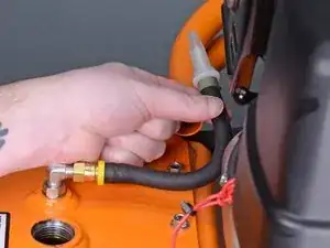
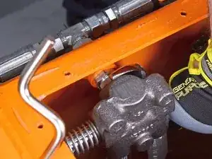
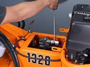
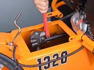
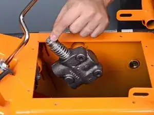
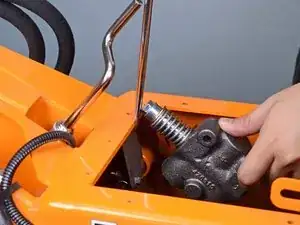
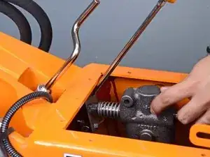
    • Using a long flathead screwdriver, pivot one end off of the edge of the tank, compressing the plunger assembly on the actuator valve.

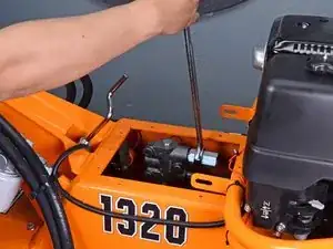
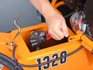
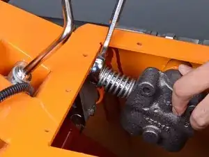
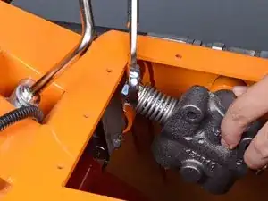
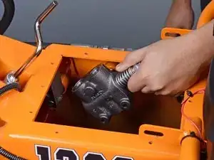
    • While the plunger assembly is compressed, rotate the actuator valve down, past the edge of the tank, and onto the strike plate.

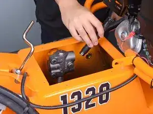
    • Repeat the last two steps to continue to loosen the actuator valve from the tank fitting.

  24. x5eRCYIEvGcUrr1t
    x5eRCYIEvGcUrr1t
    o2uiH4g4YsR4fSmU
    jgMNNsEXN3fMpFkG
    • Reassembly tip: In order to bring the plunger assembly backwards, up and over the tank edge, use an open-ended wrench to compress the plunger assembly while rotating the actuator valve.

  25. Nqsq1sRsLMi6uMNQ
    Nqsq1sRsLMi6uMNQ
    RZ6PykOG3scLd6qp
    • Remove the actuator valve.

  26. BEo6BFAdlEjpFlca
    • Use a 7/8 inch wrench to remove the tank fitting.

    • During reinstallation, install the fitting as shown, with the smaller, stationary nut facing the tank wall.

Conclusion

To reassemble your device, follow these instructions in reverse order.

Carsten Frauenheim

Member since: 10/03/20

110978 Reputation

0 comments