Introduction

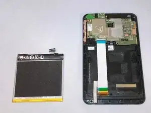
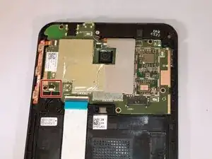
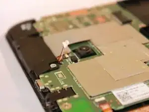
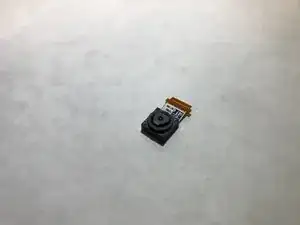
The rear facing camera is used to take photos from the tablets rear orientation. The camera may stop taking photos and videos clearly. This can be replace fairly easily, but the motherboard needs to be removed first.

  1. wshFKBQaCZ4MdTHR
    wshFKBQaCZ4MdTHR
    DZ3MPQiCrJvkNmrE
    sHX4NYVSUxERVKEG
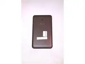
    • Power off the device before disassembly.

    • Be gentle; excessive force can result in a damaged or cracked screen.

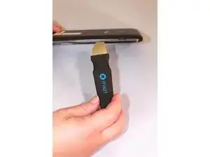
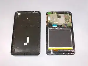
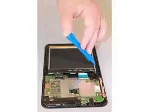
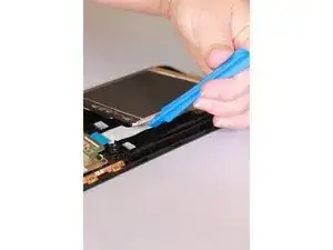
    • Gently pry a Jimmy all around the seam of the device until the back panel detaches.

  2. pWeUSIcAVA2cYwKR
    pWeUSIcAVA2cYwKR
    R64ps6fN2ag52yJP
    xQTsaYXTqLZ4Z5hG
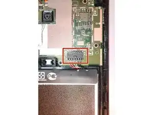
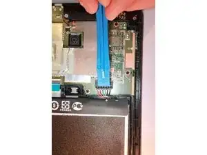
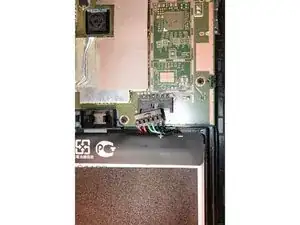
    • Use an iFixit opening tool to gently push the black bundle cable connector in a forward motion until it loosens without pushing down on the bundle cable connector.

  3. 4XnUa213HGOJPZuP
    4XnUa213HGOJPZuP
    KESoKAVtJhKmjFMf
    sRWtMIbiBJjBMsoC
    • Use the plastic opening tool to pry around the edges of the battery.

    • The battery should be laying freely in its port.

    • Lift the battery out of its port.

  4. DM2HvgICnkHFaWAn
    DM2HvgICnkHFaWAn
    BhkSsQW31uGR1KCM
    jwCyCrGVdNVmJ1lK
    • Use a plastic opening tool to slide the white cable connector completely out of the port.

  5. vEhxqHsNkKrUHyLO
    vEhxqHsNkKrUHyLO
    tkMLhnNDgHHuQGyn
    oYTERuaVHXSSPSpY
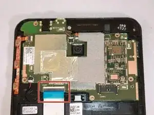
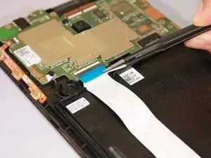
    • Flip up the beige clip to loosen the cable.

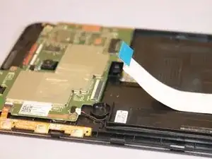
    • Use the wide nosed tweezers to pinch the blue tab attached to the ribbon cable.

    • Pull the blue tab gently in a lateral motion until it is completely out of its port.

  6. QJenoiJ6eOnRgpEU
    QJenoiJ6eOnRgpEU
    uBKoCdUxQF4Nndyl
    AXymE64JTYaGiIJR
    • Use the wide nosed tweezers to gently pull out the orange ribbon inserted in the port on the motherboard.

  7. 2TIUXrwgfGArXZME
    2TIUXrwgfGArXZME
    GiOrGREgkvAUTM12
    L1E5H5aWbqHJJw1t
    • Use a plastic opening tool to push the white cable connector out of its port in a side to side motion.

  8. PTVpGggcDiZSA11X
    PTVpGggcDiZSA11X
    XnHifQiDQfCDlvYO
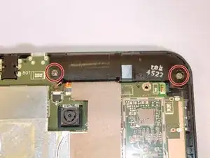
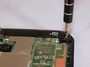
    • Use the Phillips #000 screwdriver to unscrew the seven screws.

    • There should be two silver and five black screws.

  9. u11nKjvYpfMJEujK
    u11nKjvYpfMJEujK
    ewKyXKitTWJThRbb
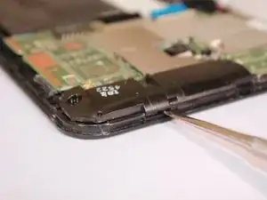
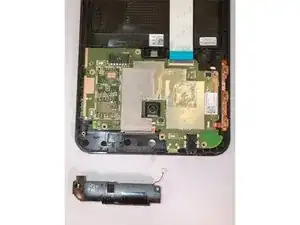
    • Once the screws are removed, the speaker component will be loosely laying in the track.

    • Use the metal spudger tool to remove the speaker by gently lifting the edge of it.

  10. ENPDMwRVnqsG5RSV
    ENPDMwRVnqsG5RSV
    EiWIGQr6GeROmQqR
    x4lGvjIVV2XUn2gM
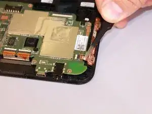
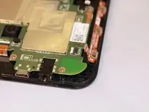
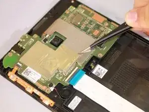
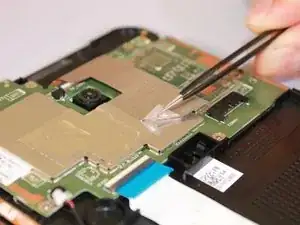
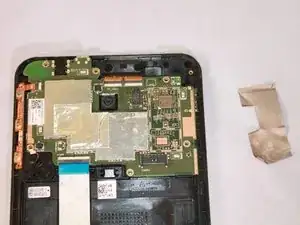
    • Remove the silver tape on one corner with the needle nosed tweezers, and remove the tape from the motherboard.

  11. PQEphgBKciAG4oNZ
    PQEphgBKciAG4oNZ
    B2XP2CurhaAouOBu
    jqHlNQlTMc52W6IV
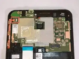
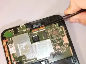
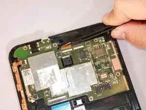
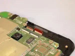
    • Use the needle nosed tweezers to gently pull both of the orange ribbon cables out of their ports.

  12. aZU5BGUIx6MrvgCk
    aZU5BGUIx6MrvgCk
    ZOmXKPevfWld2EXG
    ri6d1EUZMPBSRiET
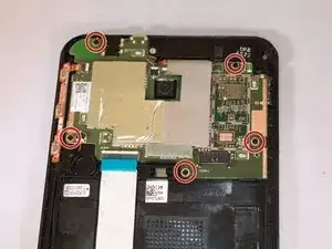
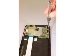
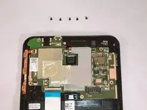
    • Use the Phillips #000 screwdriver to unscrew all five screws.

  13. DpSnelk5cCGGYJAM
    DpSnelk5cCGGYJAM
    Om6JBafcWvDdfb6O
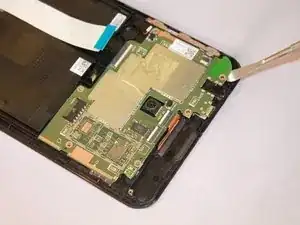
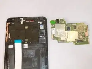
    • To uninstall the motherboard, use the metal spudger tool to lift it out of the device.

  14. pIQr2eka2MC2pgRP
    pIQr2eka2MC2pgRP
    n2ZsnR5fIEgjnJMw
    hgT6VKHuykrQkpeA
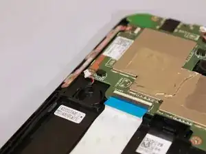
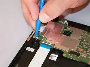
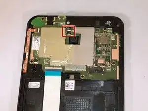
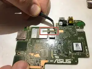
    • Gently remove grey tape that is holding down connector for camera using the tweezers.

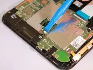
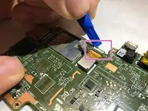
    • When tape is removed, use the plastic prying tool to gently unlock connector between camera wiring and motherboard. The connector lock rotates upward away from motherboard to release.

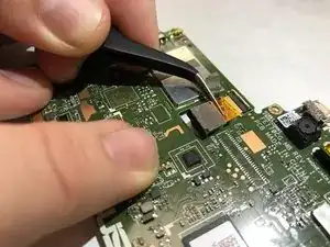
    • Carefully remove camera from motherboard using tweezers by pulling directly upward. Camera should release easily without much resistance.

Conclusion

To reassemble your device, follow these instructions in reverse order.
Thomas Brooks

Member since: 04/03/17

301 Reputation

0 comments