Introduction
Although there are several ways this task could be accomplished, this guide walks through the most appropriate steps to complete the task without damaging the fragile components. Read instructions carefully to reach success.
Tools
-
-
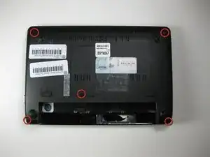
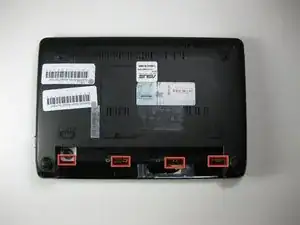
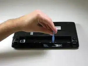
Use a plastic opening tool to pull up the four metal latches in the battery cavity that is located on the bottom of the laptop.
-
-
-
Flip the laptop over, and open the display.
-
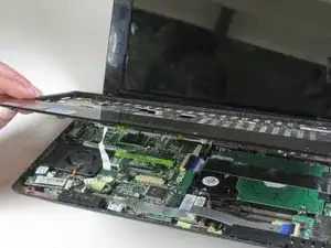
Use a plastic opening tool to lift the edge of the keyboard that is nearest to the screen.
-
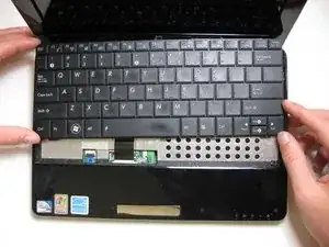
Gently lift the keyboard and slide it toward the screen.
-
-
-
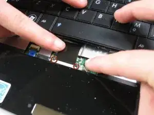
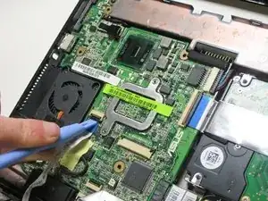
Use a spudger tool to release the tabs on the ribbon cable ZIF connector that is attached to the underside of the keyboard.
-
Once the ZIF connector tabs have been released, remove the keyboard.
-
-
-
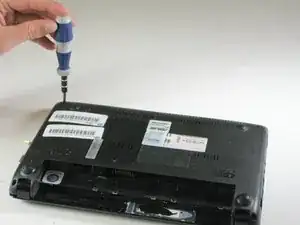
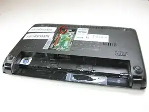
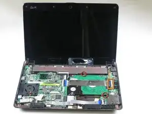
Remove (6.65 mm) screw next to RAM.
-
Identify and disconnect touch pad ribbon cable which can be seen through a window at the bottom edge of the metal part of the top casing (in these photos the connector shows blue).
-
-
-
Turn computer right side up, and open it.
-
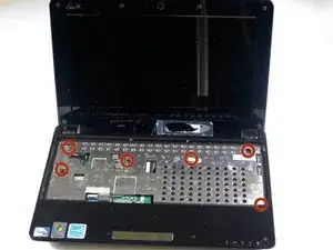
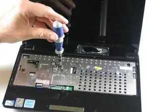
Remove 6 (5.5 mm) screws from inside covering.
-
Disconnect the touch pad ribbon cable.
-
-
-
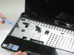
Detach each of the 5 plastic clips. Run a plastic opening tool along the underside of the top half. You will hear the 'clicks' of the clips coming undone.
-
After the clips are loose, disconnect the palmrest flatflex and remove it.
-
-
-
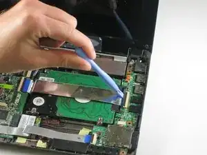
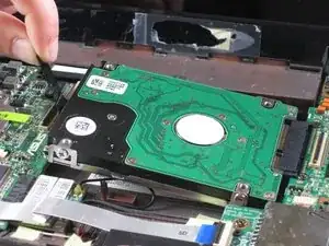
Remove the hard drive ribbon by lifting the black clips upward.
-
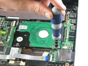
Remove (4.6 mm) screws that hold the hard drive in place.
-
-
-
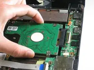
Gently pull the hard drive to the left by the black plastic ribbon. Slowly lift the hard drive up on the left and then out.
-
-
-
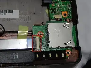
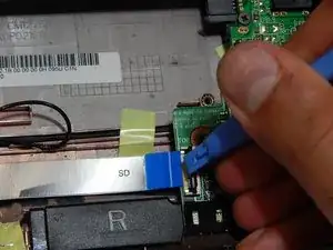
Lift the black clips using the plastic opening tool to detach the ribbon that connects the SD card module.
-
-
-
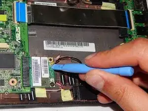
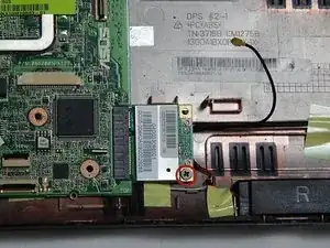
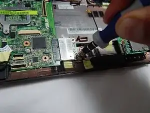
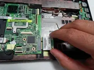
Remove this screw, which holds the wifi component in place, using the Phillips head screwdriver.
-
-
-
Pull the Wi-Fi component to the right, and then slightly upward and finally out to remove the Wi-Fi antenna.
-
To reassemble your device, follow these instructions in reverse order.
One comment
een heel duidelijke uitleg. ik zal het zelf niet proberen. ben bang dat ik met ijn trillende vingers de boel kapot ga maken.
ik had wifi verbinding maar ineens is het niet meer mogelijk om on-line te komen.
de ==internet adopter == werkt niet.
vraag mijn zwager om te helpen, anders moet ik afscheid nemen van mijn kleine computertje.
jammer.
beukeneut@gmail.com
duurt -
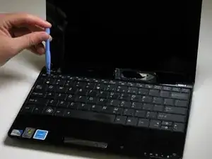
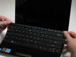
It must be mentioned that you need to put the plastic opening tool above the F1, F6, between F10 and F11 and the Insert (Num Lock) Keys . It has 4 clips in total.
Jakab Szilárd -