Introduction
-
-
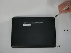
Flip the Chromebook onto its back, where there are eleven screws.
-
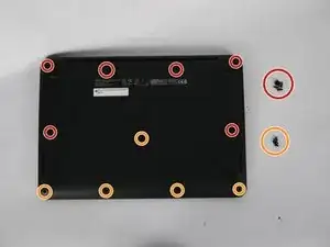
There are two variations of screws on the back panel:
-
Six 8.7mm screws.
-
Five 6.4mm screws.
-
Using your screwdriver with the J00 Phillips Head tip, remove the screws by turning them counter clockwise.
-
-
-
Once the screws are removed, flip the Chromebook back over.
-
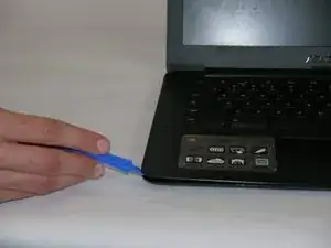
Gently remove the keyboard by starting to lift up on one corner with a plastic opening tool.
-
Follow around the brim of the keyboard until it pops off.
-
-
-
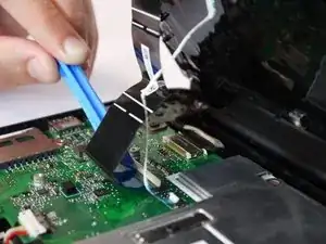
Once you remove the keyboard, it will be connected to the CPU with two tabbed connections.
-
Release the connections from the tabs gently by flipping the white flaps up until disconnected.
-
You can now pull the ribbons out from the board and remove the keyboard.
-
-
-
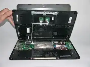
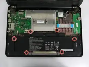
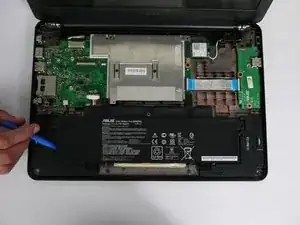
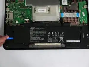
Once the keyboard is removed, the battery is located on the bottom portion of the shell.
-
The battery is held in with six 6.5mm screws on opposing sides.
-
-
-
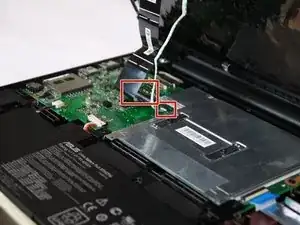
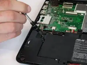
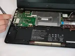
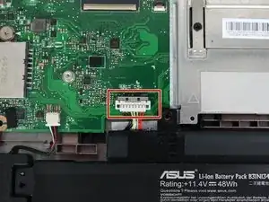
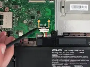
The battery is now held in with a tabbed connection to the CPU on the left side of the board. On the tabbed connection, there is a silver plate.
-
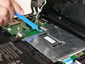
Gently push on the silver plate towards the screen until the plastic connection is free.
-
The tabbed connection should now slide out backwards.
-
-
-
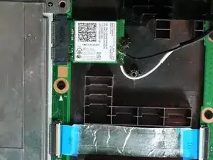
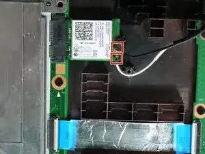
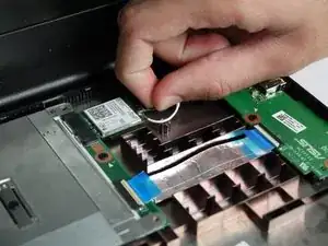
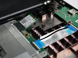
Placing the Chromebook in the upright position, the LAN card is located on the upper right side of the shell.
-
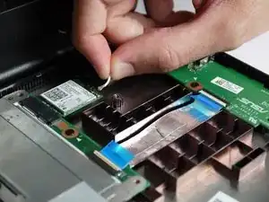
The LAN card is pinned down with 2 coaxial connectors: main power and auxiliary input.
-
To disconnect, gently pull off the two connections using an upwards motion.
-
-
-
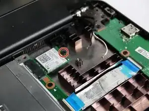
On the right side of the LAN card is a 3.4mm Phillips head screw.
-
Using the J0 Phillips Head Tip from your tool kit, remove the screw, turning counter clockwise until the screw is free.
-
-
-
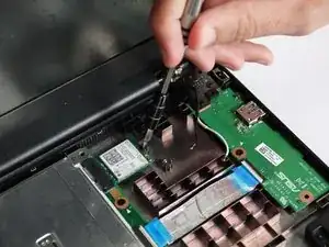
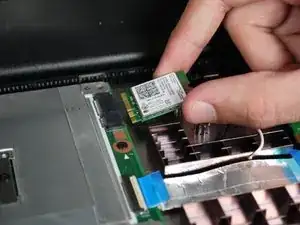
At this point, the LAN card is only connected to the CPU.
-
To remove, gently slide out the LAN card from the CPU’s input clip.
-
The LAN card is now disconnected.
-

To reassemble your device, follow these instructions in reverse order.