Introduction
Removing the logic board is a very simple procedure. Hopefully you never have to do this to your Apple TV. Just a note... There is nothing wrong with my Apple TV. I made this guide for those that may need to use it one day. My Apple TV is still running well
-
-
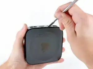
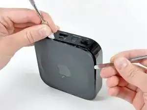
Use a spudger to pry the bottom cover off the Apple TV.
-
It may be necessary to use two spudgers (one to hold it open while you pry with the other one)
-
-
-
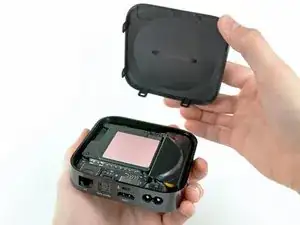
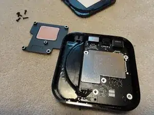
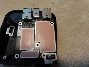
Remove the pink thermal pad. (I already removed mine)
-
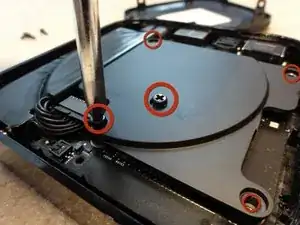
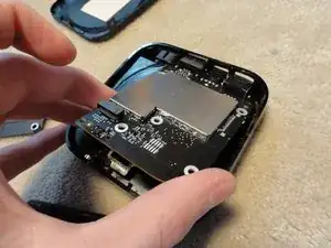
Remove the five philips #1 screws securing the heatsink and logic board to the upper casing.
-
-
-
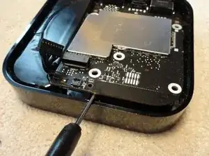
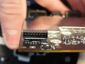
Use a flathead screwdriver or spudger to tilit the logic board to an angle so you can grab it with your hands
-
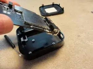
Holding the logic board by it edges, lift it up slightly.
-
And remove
-
Thats all. The logic board has been removed. Just follow the steps (Step 1-5 in reverse to install the board)
-
-
-
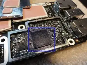
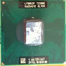
The chip with the grease on is the Apple A4 chip. The thermal pad took the silkscreen off, so its hard to read.
-
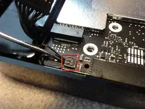
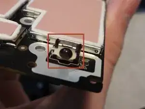
The The black ball surrounded by meta is the IR Remote sensor.
-
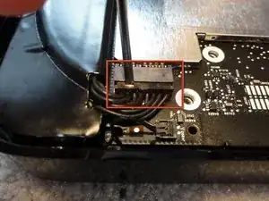
In the third picture, the power connector and LED status connector are shown.
-
-
-
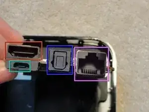
HDMI Port
-
Micro USB Port (used for diagnostics, and service)
-
Digital TOS Link out (Optical Out)
-
Gigabit Ethernet
-
To reassemble your device, follow these instructions in reverse order.
You can also use opening picks ;)
Jace Holmes -