Introduction
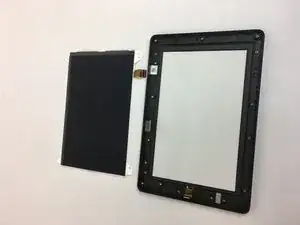
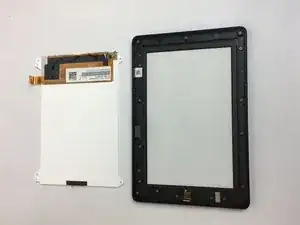
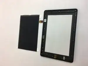
In this guide, we outline how to properly disassemble this device and replace the LCD display screen.
Tools
-
-
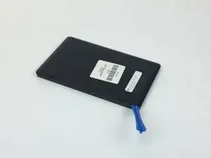
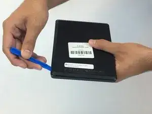
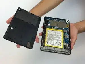
Insert the plastic opening tool behind the rear case to free the clips holding the case together.
-
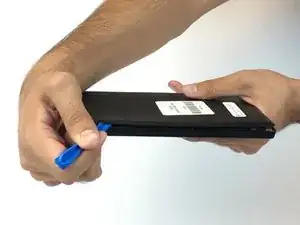
Work your way around the device to free all the clips.
-
-
-
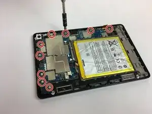
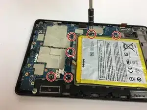
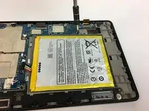
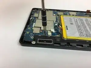
Remove the six black screws located around the battery and the speaker with the T5 Torx screwdriver.
-
Make your way around the battery and speaker to remove all of them.
-
-
-
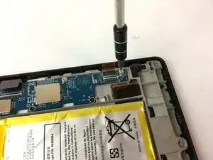
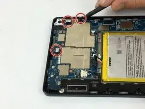
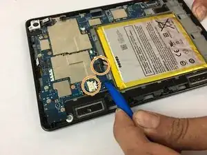
Carefully unplug the three wire connections by placing a plastic spudger under the connections and lifting up.
-
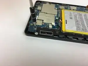
Disconnect the battery and speaker connections by placing the round handle spudger under the wires and lifting up and out.
-
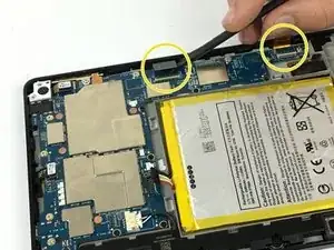
Disconnect the display connections from the motherboard by using the plastic spudger to lift the clamp holding the ribbon cable. Then, using the tweezers, grab the ribbon wire and pull away from the motherboard.
-
-
-
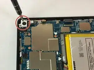
Remove the two screws holding the rear camera in place using the T5 Torx screwdriver.
-
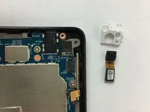
Once freed from the screws, gently lift and remove the rear camera.
-
-
-
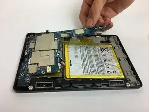
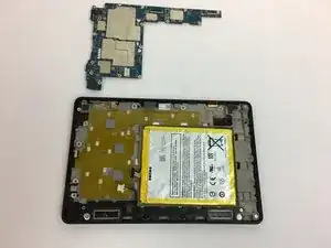
Now the motherboard is free to be removed.
-
Lift the motherboard up to remove it as shown in the picture.
-
-
-
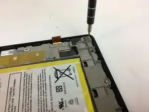
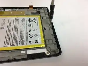
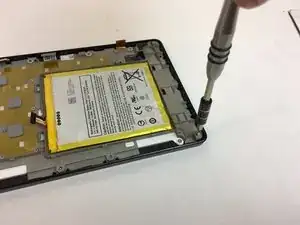
Following the bottom edge of the device, remove the (3) T5 hex silver screws with the T5 torx screwdriver.
-
-
-
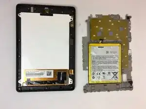
The motherboard chassis can now be removed to reveal the display screen.
-
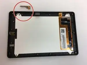
Remove the volume button components.
-
-
-
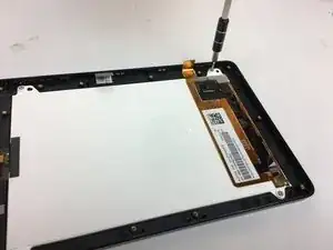
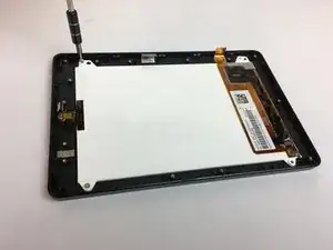
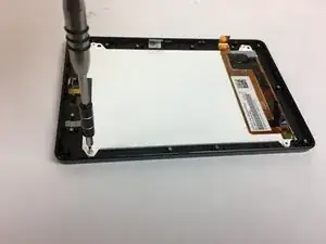
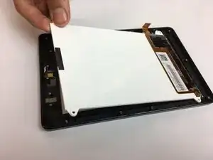
Remove the (4) T5 hex silver screws in the corners of the display screen using the T5 torx screwdriver.
-
One comment
finding it very difficult to source a new touch screen for this model.
colin -
