Introduction
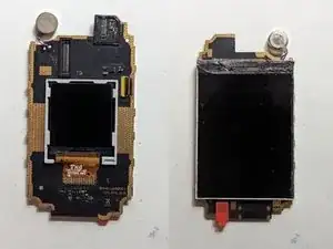
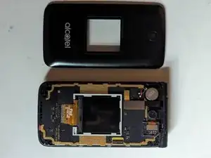
The front and rear screens are fused into a single assembly and cannot be replaced individually. This guide will show how to replace the complete assembly.
Tools
-
-
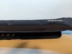
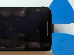
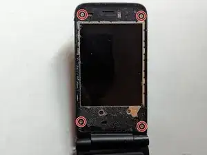
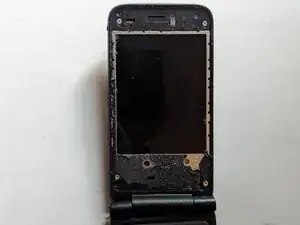
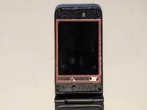
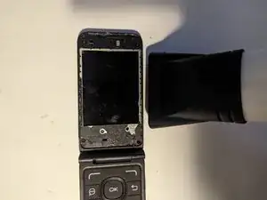
Heat the screen cover with an iOpener, a heat gun or even a hair dryer to soften the adhesive holding it to the display frame.
-
-
-
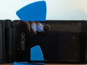
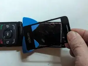
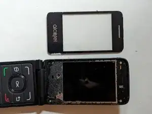
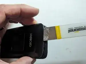
Use plastic picks to separate the adhesive. Metal is not advised as it will scratch the plastic material the cover is made of. Add more heat as needed.
-
-
-
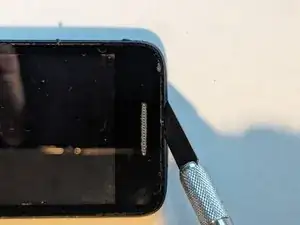
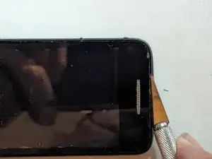
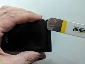
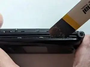
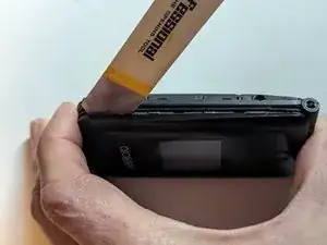
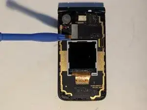
Starting at the hinge side, insert a metal opening tool between the rear cover and the display's frame.
-
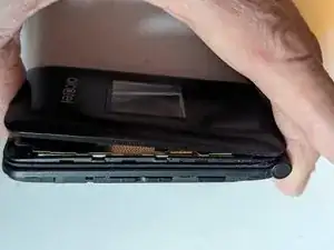
Continue down the side of the phone, releasing clips as you go.
-
-
-
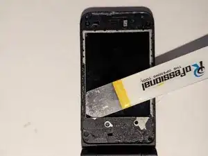
The screen is held onto the display frame with adhesive around the outside edge of the LCD, with a thicker bar of adhesive along the bottom edge as shown.
-
-
-
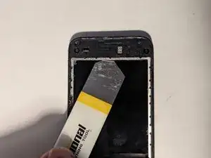
Heat the edges of the LCD frame to soften the adhesive holding it in place. A hair dryer, heat gun or iOpener will all work fine.
-
-
-
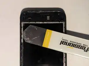
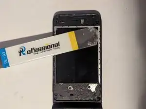
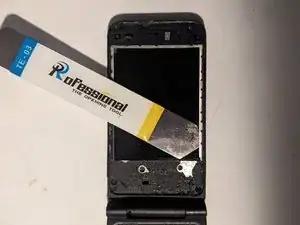
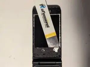
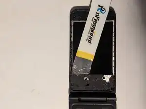
Insert an opening tool between the lip of the frame and the LCD. Use it to slice the adhesive along the top edge.
-
Now go along the side edge.
-
-
-
Finally, slice the adhesive along the bottom edge. Note that you'll need to go much deeper as there is a wider strip of adhesive along that edge.
-
-
-
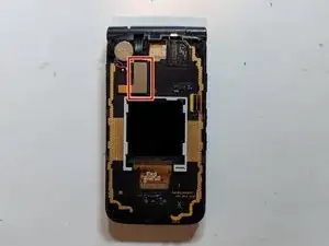
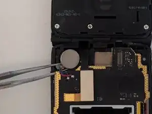
The vibrator is lightly glued to the display frame. Gently pry it loose, mindful of the wires attaching it to the LCD assembly.
-
-
-
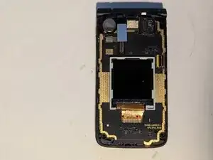
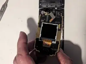
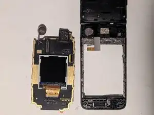
Lift the LCD assembly from the display frame. There will probably be several strands of adhesive you'll need to separate as you pull it apart.
-
To reassemble your device, follow these instructions in reverse order.
