Introduction
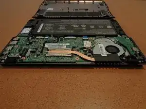
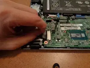
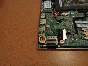
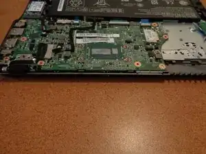
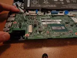
Use this guide to replace the motherboard in an Acer C720 Chromebook. Basic knowledge, and use of a screwdriver is all that is needed to complete the guide along with careful observance of possible hazards such as electrical discharge or shock. This repair can resolve issues with memory, power issues not related to the power supply, or many of the other components of the C720.
The replacement process works through removal of the underside chassis of the device, the internal components that block removal of the motherboard such as the fan, SSD, and the wireless card cables. The removal of all other cables, and the remaining two screws. Then the removal of the motherboard itself.
Tools
Parts
-
-
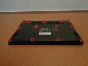
With the device bottom side up we can remove the 13 6mm screws that hold the bezel in place using a #0 Phillips screw driver.
-
-
-
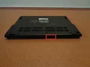
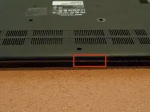
To remove the underside chassis use your fingers (or the card) to gently lift up on the small crevice (this is between the hinges for the display). Once the first half has been removed run the card along the perimeter of the chassis as you gently apply a little force as you are pulling upwards with your other hand.
-
-
-
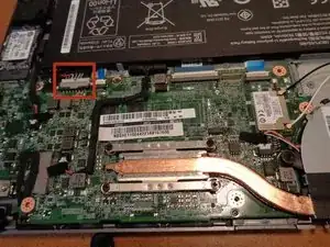
Using the card push on the sides of the battery cable bit by bit switching from side to side until the cable has been fully removed. The cable has a white end, and multicolored wires coming from it.
-
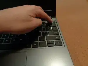
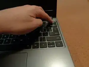
Once the connector has been removed gently flip over the device and hold down the power button for a few seconds to remove any remaining power. This will prevent any electrical shock moving forward.
-
-
-
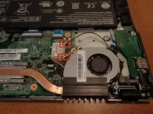
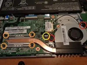
Before we remove the fan we need to remove the cables for the wireless NIC card that go over the fan. They are the black and white cables shown in the red squares. To remove them grab them as close as you can to the placement of the red circles and then gently lift up. It will not take much to remove them from their terminals.
-
Once removed from their terminals trace the cables through the fan and set them over to the side so we can remove the fan in the next step.
-
-
-
There are a total of six screws needed to unscrew for the fan to be removed. The screws themselves are built into the fan assembly and cannot be removed. Using the #0 Phillips screwdriver unscrew all of the screws.
-
Unscrew these as normal.
-
Remove these in order to the number directly next to them starting with 1 and goes up to 4. This prevents stripping of the threads on the screws.
-
The fan cable is now all we have left before we can remove the fan. To remove the cable use the card in a similar manner as the battery cable. Pull up on the tape just enough to separate it from the motherboard but not hard enough to pull on the wire. Push at the sides of the terminal with the card until fully removed from the connector.
-
Now we can remove the fan. Lift up on the fan to pull it out, and place it face up so that the thermal paste does not get on the table.
-
-
-
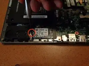
Remove the single screw that holds in the SSD using the #0 Phillips screwdriver.
-
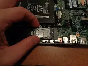
While holding the sides of the SSD gently pull it out and away from the motherboard..
-
-
-
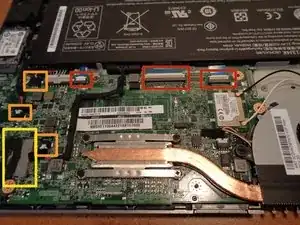
Remove the ribbon cables by using your fingers or the card to very gently pull up on the latches (white or beige colored) to the direction away from the battery. Then by using the blue plastic ribbon pull the cables out towards the battery to remove them from their terminals.
-
Remove these cables by first lifting up the table that holds them down with just enough force to remove the tape from the motherboard but no more. Then remove the cables by using the card on the sides moving back and forth between sides to gently remove the cable from it's terminal. As done for a few of the earlier cables.
-
The last cable is the only cable like this for the C720, and it's removal can be a little tricky so be patient while removing it to avoid damage as these cable types are easy to damage.
-
If you look closely you can see that there is a little bit of tape that sits just over the edge of the terminal around where the yellow box's right edge is. Peel this tape back very slowly until it reaches the black part of the cable.
-
Now pull on the tape towards the left side of the device with the battery oriented away from you as it is in the picture.
-
-
-
All that is left is to remove the two screws that hold in the motherboard.
-
Remove this 3 mm screw using the #0 Phillips screwdriver. The head of this screw is a bit wider than all of the rest.
-
Remove this 3 mm screw using the #0 Phillips screwdriver.
-
-
-
Taking care not to catch the motherboard peripherals such as the USB, microphone jack, and DC-in on the left hand side of the motherboard on the chassis pull out the motherboard by moving it a little to the right and then pulling up.
-
To reassemble your device, reinsert the motherboard with the USB, headphone jack, and DC-in side first into their respective holes. This will ensure that the motherboard fits correctly. Then follow the above instructions in reverse order.
