Introduction

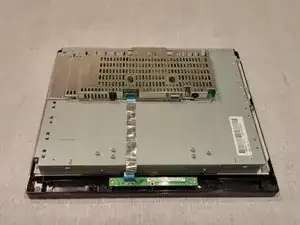
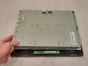
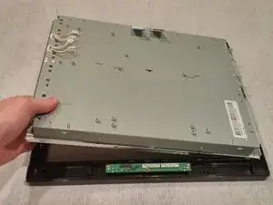
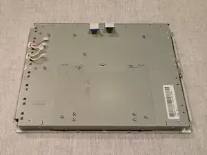
This guide will demonstrate the steps needed to disconnect and replace the LCD in the Acer AL1714. A malfunction in this part can cause possible issues with the ability to view images on your device.

  1. GuhDovKVFpVjOLDw
    GuhDovKVFpVjOLDw
    PQCw44WfWwJDUusJ
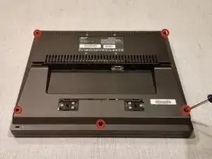
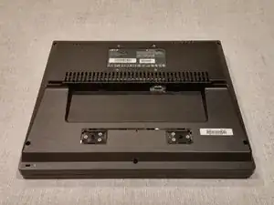
    • Turn the monitor facedown.

    • Unscrew the 5 screws holding the back cover on.

    • (This may require flipping the monitor over and shaking the screws loose once they're already unscrewed)

  2. cfIuSCM1YVIERmgj
    cfIuSCM1YVIERmgj
    BAuEZ1UTIOt1mGL2
    gngDG5NhNMNxBTGF
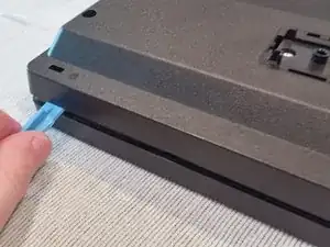
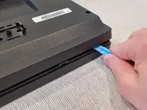
    • Take the edge tool or a metal ruler and insert it into the bezel.

    • Apply pressure and push down.

    • Do the same to the right side.

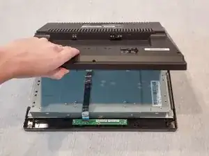
    • Once the side of the bezel facing you is decoupled, take the back cover and pry it loose.

    • (This will require some force, you will hear a loud popping/snapping noises)

  3. e5VvPJ2DldWRTRaK
    e5VvPJ2DldWRTRaK
    YIZewlAXbLnWNrdC
    NIUREV4DIh2FADvg
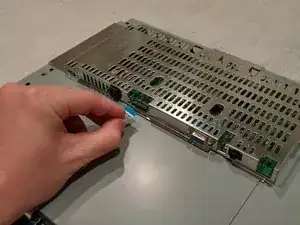
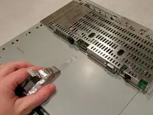
    • Remove the Power Button Circuit Board Flat Flex Cable from the Power Supply board under the metal cover.

    • Pull the cord back and out of the way.

    • (It may be stuck down with adhesive)

  4. aQB52Bpjc3pPqtb3
    aQB52Bpjc3pPqtb3
    IRZKqkaEriSXkS6L
    vLAXkGpXAawmCTcn
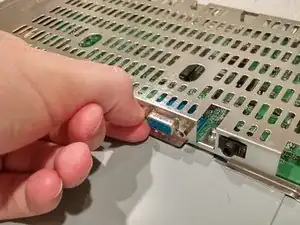
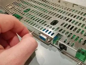
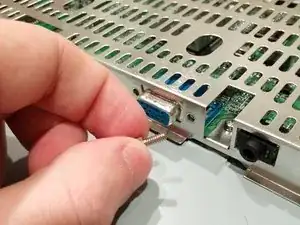
    • Unscrew the cord anchors for the VGA port.

    • (Use needle nose pliers if they're too tight for removal by hand)

  5. MOwZpeBTaOnYcjPf
    MOwZpeBTaOnYcjPf
    IFijyvRqf61wXSoV
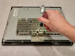
    • Turn the monitor around.

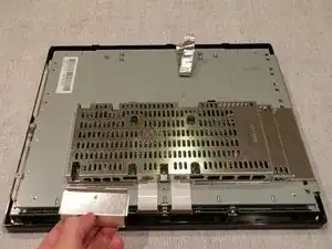
    • Unscrew the 1 screw holding the Flat Power Cable cover in place.

    • Lift up and remove the Flat Power Cable cover.

    • (Careful: it may be sharp)

  6. M1RybRpVvQUgguGe
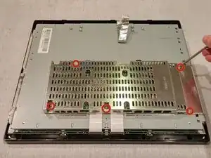
    • Unscrew the 5 screws holding the metal cage on.

  7. ppyOEQOv4RhgIMye
    ppyOEQOv4RhgIMye
    YgkRUmVoJfDYu4Qo
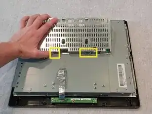
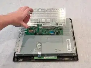
    • Turn the monitor around.

    • Lift up on the back of metal cage, slightly.

    • Pull the cage toward self.

    • (Must be careful to free cover of the VGA port and power supply input)

  8. kQMNscm6ZiiPYb6o
    kQMNscm6ZiiPYb6o
    LLPmynpkWyo1MERF
    ytRVvKfPHVvwSP5g
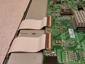
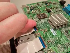
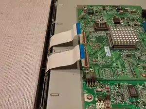
    • Lift up on the Flat Flex Cable holder tabs to release the cords.

    • Lift up on the Flat Flex Cables and bend them out of the working area.

  9. H2h6sRpZ3P2LWHbR
    H2h6sRpZ3P2LWHbR
    PjCCJvL5dXSlVJnh
    kER1HDGhWqJZKw34
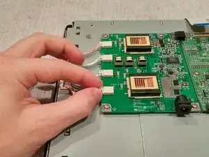
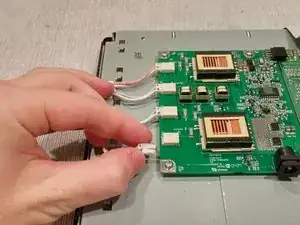
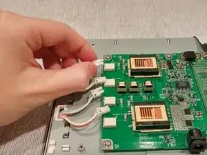
    • Unplug the 4 backlight wires from their ports on the Power Supply board.

    • (Considering their size, the best way to unplug the backlight wires is by slowly jiggling and pulling the wires out of place)

  10. EscQXmlEOOwTtRlQ
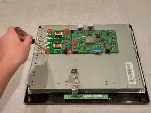
    • Unscrew the 5 screws holding the Power Supply and Video Display boards.

  11. p2fWtGSqVVaihLJm
    p2fWtGSqVVaihLJm
    FXktdlPVOjoAwOZt
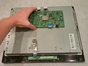
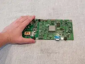
    • Lift and remove the joined Power Supply and Video Display boards.

  12. SrqX33ZGO3FDVbfT
    SrqX33ZGO3FDVbfT
    nbikW21RfLyfXMoe
    TF1fY5gAqPDcCPQK
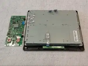
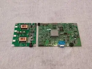
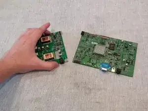
    • Carefully detach the Power Supply and Video Display boards at the connector joint.

    • (This step is not necessary to replace the LCD Module. This step is only a safety precaution so as not to bend or break the Power Supply connector joint)

  13. xPFKpgixjMVOLPCt
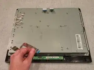
    • Remove the Flat Flex Cable from the Power Button Circuit board.

  14. kDtb5jFm5NIWBYxS
    kDtb5jFm5NIWBYxS
    rveAaFXUhB6wJW24
    LXDv5wTLLAeuaGR6
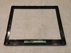
    • Grasp, lift, and remove the LCD Module from the front panel.

  15. UMmXYoXAVvecbLpa
    • The final product with the LCD Module removed.

Conclusion

To reassemble your device, follow these instructions in reverse order.
Christopher Kelly

Member since: 25/09/14

590 Reputation

0 comments