Introduction
This guide delivers the complete steps to replace missing buttons and/or the keypad for the ATT CL2940 black corded speakerphone. The tools are listed and required to successfully complete this project.
This project is necessary for individuals who need to replace the buttons or keypads for this device. It can save you money and the hassle of switching to a new device.
If you need more information on how to troubleshoot this device, please follow this link: ATT CL2940 Troubleshooting. It has several troubleshooting instructions that will help you evaluate the technical needs of your device.
Warnings to adhere to when completing this project:
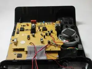
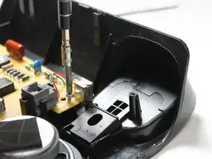
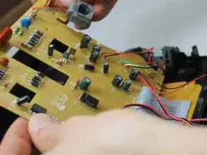
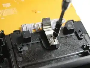
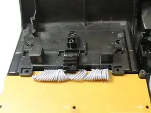
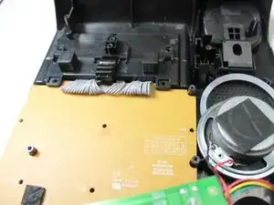
When setting the back panel down, be careful to not rip any of the wires off of the internal components.
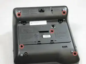
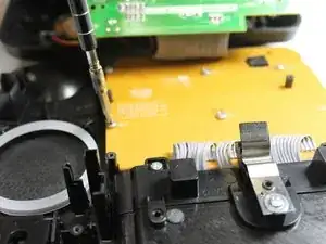
Keep the screws for the upper and lower level motherboard separated.
-
-
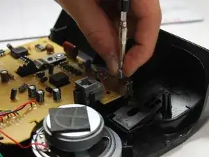
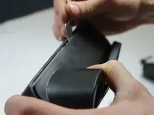
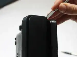
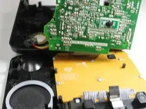
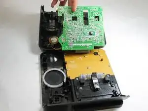
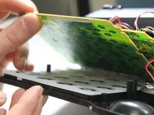
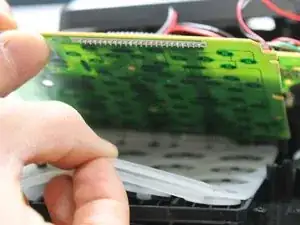
Push the Button Panel upward and pull it out.
-
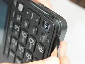
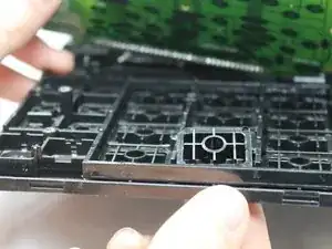
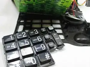
Replace the entire Button Panel or a single defective button.
-
To reassemble your device, follow these instructions in reverse order.
One comment
Great explanation! Where would you recommend buying replacement buttons for the phone? Thanks