Introduction
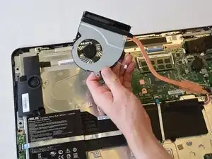
This guide will walk you through the steps necessary to replace the heat sink and fan assembly in the ASUS Portable AiO PT2001. No special skills are required.
The only tool you need is a Phillips screwdriver.
Tools
-
-
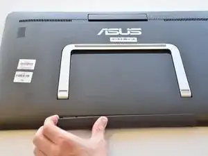
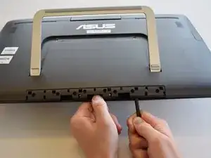
Remove the grey scuff guard at the bottom of the PC by pressing down on it, and pulling it away.
-
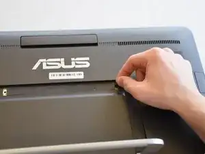
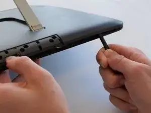
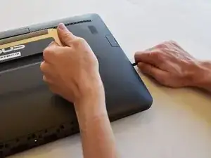
Lift the hinge and remove the grey rubber tabs on either side of the PC’s model information.
-
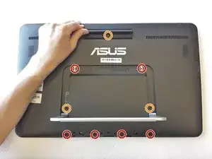
Remove the two 7.62mm Phillips #1 screws beneath the rubber tabs under the hinge and the four 7.62mm Phillips #1 screws where the scuff guard was removed.
-
Remove the two 4.74mm Phillips #1 screws under the hinge (near the hinge joints) and a 4.74mm Phillips #1 screw under the handle.
-
-
-
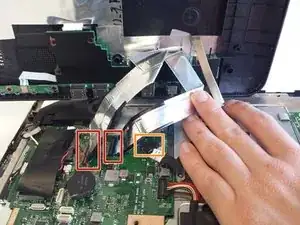
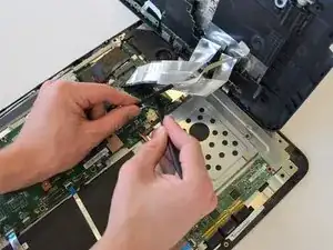
Disconnect the three cables connecting the back panel ports to the motherboard.
-
Flip up the locking latch holding the two ribbon cables with a plastic opening tool and pull the cables out.
-
Gently wiggle the third connector out of its socket.
-
-
-
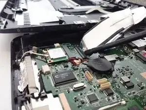
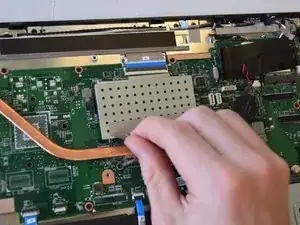
Remove the tape attached to the heat sink and the metal enclosure.
-
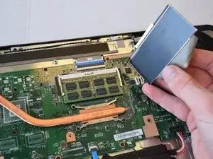
Lift the metal enclosure off.
-
-
-
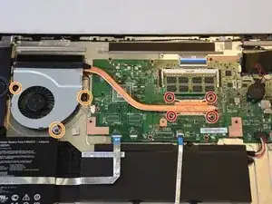
Remove the four 3.0 mm Phillips #1 screws attaching the heat sink to the motherboard.
-
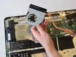
Remove the three 4.0 mm Phillips #1 screws connecting the fan to the device.
-
To reassemble your device, follow these instructions in reverse order.
How to open the 2 screws at the root of the handle? (The orange colored in your chart) There are two squares gray toppers. Which type of tools to use to open that toppers? Thank you so much for this instruction.
adazhu -