Introduction
If you have received our Linear Rail Kit before 1/20/23 please follow this guide: Raptor X Axis Linear Rail Install
-
-
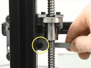
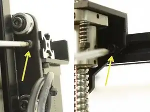
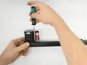
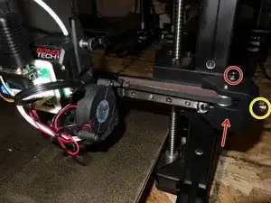
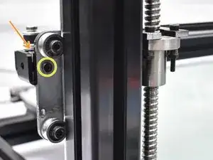
Using a 8mm open end wrench, loosen the bottom inner wheel eccentric locknut. Back it off a few turns.
-
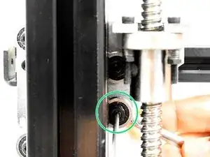
Using a 7mm closed end wrench hold the nylock nut on the front of the X/Z bracket and loosen the eccentric wheel shaft with the M2.5 hex.
-
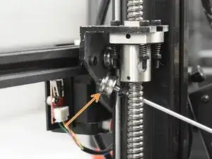
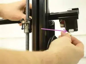
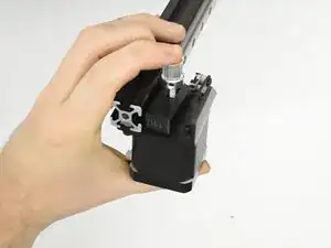
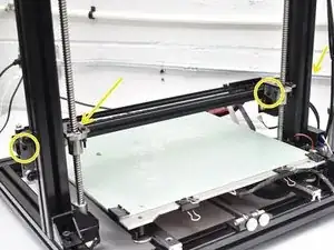
Fully remove both lower inner wheels. They will not be used.
-
-
-
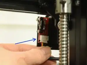
Unplug the X End Stop then the X Motor (this can be done before or after X Axis removal depending on your access)
-
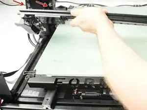
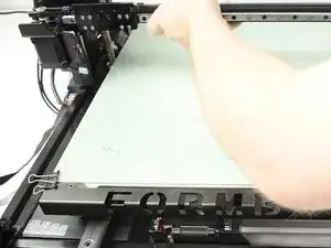
Remove the assembly by loosening the cap screws from the back of the machine. The T nuts just need to align parallel to the slot.
-
Be sure the X Motor is unplugged
-
-
-
Use a knife to open the box and remove the foam bundle. There are rubber bands to keep it all together during unboxing. Remove the rubberbands and set aside. Please repurpose them.
-
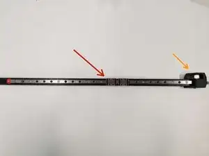
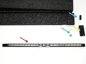
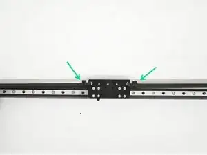
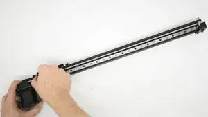
Remove the top foam to reveal your Linear Rail Upgrade! You should have received everything needed to install the upgrade.
-
1 Assembled Linear Rail Upgrade
-
1 X Carriage Plate
-
1 X Axis Idler Assembly
-
8 of M3x4 SHCS (socket head cap screw)
-
1 printed motor pulley spacer
-
-
-
With M2 hex, loosen the motor pulley set screws and insert the printer spacer under the pulley.
-
With the pulley flange facing down and pinching the pulley spacer firmly, position one set screw to align with the machined flat on the motor pulley shaft and tighten that one first. Then, tighten the second set screw.
-
Install the X Axis Motor / bracket onto the new 2020 frame with the pulley facing up when the linear rail is facing forward. The end stop should be facing to the right.
-
-
-
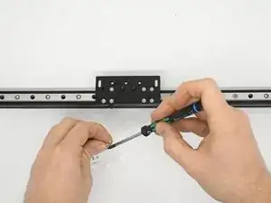
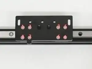
Install the X Carriage Plate. Using an M2.5 hex, start all 8 cap screws a couple threads before tightening any then tighten in an X pattern
-
Make sure the carriage moves smoothly in both directions in full travel.
-
-
-
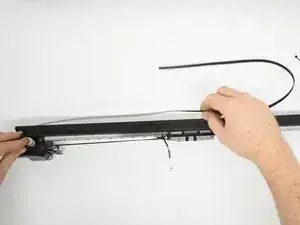
Route one end of the belt through the front of the belt slot on the X Carriage Plate and fold over about ½”. Using a cable tie, secure that end in place, making sure the teeth on the belt mesh together to hold tight.
-
Run the belt around the opposite side pulley and back to the open slot repeating the process, this time pulling the belt tight with your hands or needle nose pliers before securing with a cable tie.
-
-
-
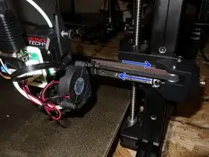
Loosen the screws on the top and bottom of the X Idler assembly to allow for belt tension adjustment
-
The printed Idler mount and tension can be adjusted by the M5 screw on the end of the Idler Mount.
-
Once tension is set, tighten the top and bottom screw to hold the tension
-
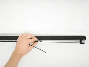
Add a second cable tie to both sides next to the others.
-
-
-
Plug the X Motor back in
-
Make sure the T nuts are still in place and parallel to the X Axis
-
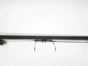
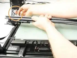
Install the new X Axis Assembly
-
While holding in in place, tighten the right outside cap screw and make sure it clamps the assembly in place before letting go.
-
Repeat for other 3 screws
-
-
-
There are 4 cap screw/ t nuts securing the X Axis in place. Using an M3 hex key, you can tighten the 4 screws (inner and outer + left and right)
-
You can line the right side (idler) so it is flush with the X/Z bracket.
-
To reassemble your device, follow these instructions in reverse order.