71
18
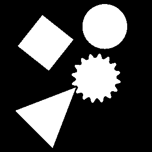
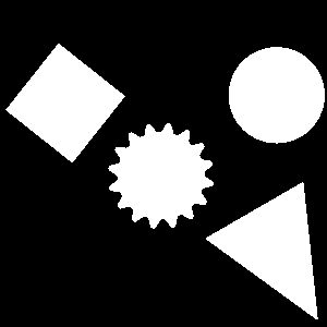
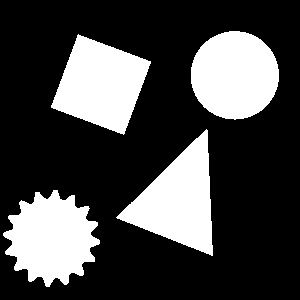
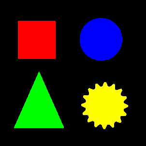
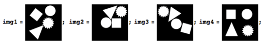
Using Algodoo and Paint I made these six 300×300 monochromatic images of four convenient shapes:
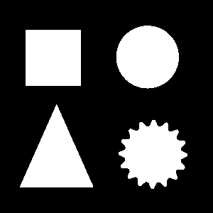
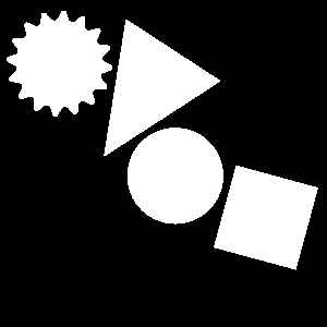

This class of images has the following properties:
- They are always 300×300 pixels, monochromatic (black and white only), and have exactly four white regions that correspond to a square, a circle, a triangle, and a gear.
- The shapes never overlap or touch each other, nor do they touch the image border or go out of bounds.
- The shapes always have the same size, but they may be rotated and positioned in any way.
(The shapes also have equal areas, though when rastered like this their pixel counts are unlikely to be exactly equivalent.)
Challenge
Write the shortest program or function possible that takes in the filename of such an image and turns all the white pixels...
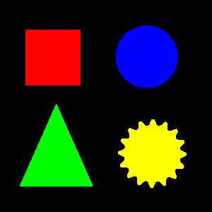
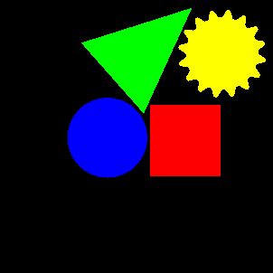
- red
(255, 0, 0)if they are in the square. - blue
(0, 0, 255)if they are in the circle. - green
(0, 255, 0)if they are in the triangle. - yellow
(255, 255, 0)if they are in the gear.
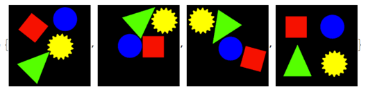
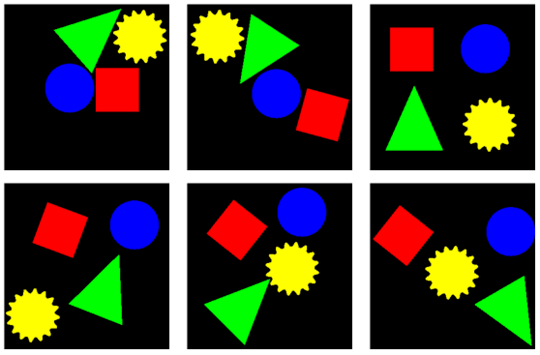
e.g.
Details
Your program should work for effectively all possible input images. (Only valid 300×300 monochromatic images will be input.) The six images I have provided are merely examples, you may not hardcode their output into your program.
You may not use computer vision libraries or functions, built-in or external. The point is to do this using your own pixel-level operations. You may use image libraries that simply let you open and modify images (e.g. PIL for Python).
You may use any common lossless image file formats for input and output as long as you stick to the color scheme.
You can take in the image filename as a function argument, from stdin, or from the command line. The output image can be saved to a new file, the same file, or simply displayed.
Scoring
The submission with the fewest bytes wins. I may test submissions with additional images to determine their validity.
Calvin's Hobbies
Posted 2014-11-01T06:24:25.470
Reputation: 84 000


May we assume the input is black & white with no anti-aliasing? If not, may we remove anti-aliasing from anti-aliased inputs? – John Dvorak – 2014-11-01T07:29:58.180
@JanDvorak Yes. By monochromatic I mean black and white only, so there can't be anti-aliasing. – Calvin's Hobbies – 2014-11-01T07:32:18.143
1
May we require a specific input format more precisely than just a file extension? Namely, I'd like me an ASCII PBM input without any comments inside.
– John Dvorak – 2014-11-01T07:42:12.267@JanDvorak Yes, that's alright. – Calvin's Hobbies – 2014-11-01T07:44:25.573
Do you want us to implement all the low-level pixel operations, or are libraries like opencv ok? I mean, there is no opencv.detectGear(), but the library is somehow designed to solve such tasks. – Falko – 2014-11-01T07:54:01.010
@Falko The low level stuff. See edits. – Calvin's Hobbies – 2014-11-01T08:00:51.977
@Quincunx "(The shapes also have equal areas, though when rastered like this their pixel counts are unlikely to be exactly equivalent.)" So I wouldn't count on their areas being a determining factor. – Calvin's Hobbies – 2014-11-01T09:08:25.577
Just checked, Blue has 6130 pixels, Green has 6157 pixels, Yellow has 6126 pixels, and Red has 6162 pixels. These values are based on the upright position image. Rotations will change these values. It is likely that they will not even be in the same order by area for each image. – Axoren – 2014-11-01T09:08:29.447
Is it okay to just dump the output file contents into STDOUT? – John Dvorak – 2014-11-01T09:39:48.390
@JanDvorak No. You actually need to save the image to a file or display it properly. – Calvin's Hobbies – 2014-11-01T09:42:17.343
Currently I'm struggling with conversion to my favourite file format. Do you have any converter that can produce ASCII PBM? GIMP leaves out spaces. – John Dvorak – 2014-11-01T10:23:44.903
Actually, I might just script a fixer... – John Dvorak – 2014-11-01T10:27:54.520
12
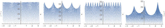
So... I was trying to solve this, and I ended up with this image. Not really sure how, but hey, it looks fancy. :P
– Doorknob – 2014-11-01T14:11:30.3102I don't want to post my solution as it's the same idea as Ell's but worse. But I just want to say this was an enjoyable little challenge to do :) – Chris Burt-Brown – 2014-11-01T19:53:24.430