Drive a hexadecimal 7-segment display using NAND logic gates

9

2

The ubiquitous 7-segment numerical display can unambiguously display all 16 hexadecimal digits as show in this wikipedia .gif

Entries for this challenge will create a circuit diagram using NAND logic gates which transforms the four bits of a hex digit to the inputs for the seven segments. The inputs for the 7 segment display are typically labelled as follows: (DP (decimal point) is ignored for this challenge)

enter image description here

Thus your circuit will need to conform to the following truth table:

Hex   | Hex Input Bit | Output to Segment line:
digit |  3  2  1  0   |  A  B  C  D  E  F  G
------+---------------+-----------------------
   0  |  0  0  0  0   |  1  1  1  1  1  1  0
   1  |  0  0  0  1   |  0  1  1  0  0  0  0
   2  |  0  0  1  0   |  1  1  0  1  1  0  1
   3  |  0  0  1  1   |  1  1  1  1  0  0  1
   4  |  0  1  0  0   |  0  1  1  0  0  1  1
   5  |  0  1  0  1   |  1  0  1  1  0  1  1
   6  |  0  1  1  0   |  1  0  1  1  1  1  1
   7  |  0  1  1  1   |  1  1  1  0  0  0  0
   8  |  1  0  0  0   |  1  1  1  1  1  1  1
   9  |  1  0  0  1   |  1  1  1  1  0  1  1
   A  |  1  0  1  0   |  1  1  1  0  1  1  1
   b  |  1  0  1  1   |  0  0  1  1  1  1  1
   C  |  1  1  0  0   |  1  0  0  1  1  1  0
   d  |  1  1  0  1   |  0  1  1  1  1  0  1
   E  |  1  1  1  0   |  1  0  0  1  1  1  1
   F  |  1  1  1  1   |  1  0  0  0  1  1  1

I think this table is accurate, but please let me know if you spot any errors.

Your score is determined by the number of 2-input NAND gates you use (1 point per gate). To simplify things, you may use AND, OR, NOT, and XOR gates in your diagram, with the following corresponding scores:

  • NOT: 1
  • AND: 2
  • OR: 3
  • XOR: 4

Digital Trauma

Posted 2014-09-11T18:23:44.183

Reputation: 64 644

this challenge seems to be about drawing a circuit diagram, and not about coding. Also, the point values per gate seem arbitrary (maybe intentionally), and using AND+NOT is 3 points, when you state NAND is only 1. – stokastic – 2014-09-11T18:32:00.370

@stokastic There are plenty of other [tag:logic-gates] challenges on this site, so I am assuming this category of challenge acceptable to the community. Many use the same scoring system. NAND logic I think explains this scoring system quite well.

– Digital Trauma – 2014-09-11T18:40:07.070

Fair enough. I hadn't seen those tags before. It just doesn't seem to really fit in 'programming puzzles' or 'code golf'. – stokastic – 2014-09-11T19:05:15.230

Can the circuit split? In other words, can you save values to variables and recall them later? – xnor – 2014-09-11T19:24:03.043

@xnor Are you talking about this sort of thing: http://codegolf.stackexchange.com/a/26235/11259? If so, the answer is yes.

– Digital Trauma – 2014-09-11T19:37:44.087

I assume they have to be 2-input NAND gates (you can't cheat by using NAND gates with more than 2 inputs each.) If you search for previous questions about NAND gates, most of them state this explicitly. – Level River St – 2014-09-11T21:45:50.927

We had to do this in my second year of undergrad engineering. No way am I doing it again for fun. :D :P My answer is: use an FPGA. :D – COTO – 2014-09-11T22:22:34.713

@steveverrill That is correct. I will clarify that. – Digital Trauma – 2014-09-11T23:52:25.120

Answers

17

Dominoes - Total Score: 243 NANDs

  • ORs used: 61 (3 NANDs each -> 183 NANDs)

  • NOTs used: 60 (1 NANDs each -> 60 NANDs)

This solution is in dominoes and required a collection of pieces of software I wrote in the course of answering Martin Büttner's two Domino related questions to produce (Golfing for Domino Day and Domino Circuits).

By modifying my Domino Circuit solver, I was able to produce a domino circuit (this file also contains the solver output and circuit skeleton) consisting of ORs, and IFNOTs where the first input is always TRUE (so it's essentially a NOT). Because there isn't much that will fit in this answer, I present the OR and NOT solutions to the truth table:

A: 1011011111101011
((-1 ifnot (2 or (1 or (-1 ifnot 0)))) or ((-1 ifnot ((-1 ifnot 1) or (-1 ifnot 2))) or ((-1 ifnot (3 or (-1 ifnot (0 or (-1 ifnot 1))))) or (-1 ifnot (0 or ((-1 ifnot 3) or (-1 ifnot (2 or 1))))))))
B: 1111100111100100
((-1 ifnot (3 or 1)) or ((-1 ifnot (3 or (2 or 0))) or (-1 ifnot ((-1 ifnot 3) or ((-1 ifnot (2 or (0 or (-1 ifnot 1)))) or (-1 ifnot ((-1 ifnot 0) or (-1 ifnot 2))))))))
C: 1101111111110100
((-1 ifnot (2 or (-1 ifnot 3))) or ((-1 ifnot (1 or (-1 ifnot 0))) or (-1 ifnot (0 or (-1 ifnot (3 or (1 or (-1 ifnot 2))))))))
D: 1011011011011110
((-1 ifnot (3 or (1 or 0))) or ((-1 ifnot (2 or ((-1 ifnot (3 or 0)) or (-1 ifnot (1 or 0))))) or (-1 ifnot ((-1 ifnot 2) or ((-1 ifnot (3 or 1)) or (-1 ifnot ((-1 ifnot 1) or (-1 ifnot 3))))))))
E: 1010001010111111
((-1 ifnot (3 or (-1 ifnot (2 or (-1 ifnot 1))))) or (-1 ifnot ((-1 ifnot 0) or (-1 ifnot (2 or 1)))))
F: 1000111011111011
((-1 ifnot (3 or (-1 ifnot 1))) or ((-1 ifnot (2 or (0 or (-1 ifnot (1 or (-1 ifnot 3)))))) or (-1 ifnot ((-1 ifnot 0) or (-1 ifnot (2 or (-1 ifnot 1)))))))
G: 0011111011110111
((-1 ifnot (2 or (0 or (-1 ifnot 1)))) or ((-1 ifnot (1 or (-1 ifnot (2 or 0)))) or (-1 ifnot ((-1 ifnot (3 or 2)) or (-1 ifnot (0 or (-1 ifnot 3)))))))

Note that the only binary operations used are OR and IFNOT, where I count each IFNOT as a NOT for scoring purposes

I added a 7-segment display to the end of the circuit and fed it into a domino simulator/gif generator. The resulting gif (which shows 'A' being displayed) took about 2 hours to generate. Because the final circuit is 1141 * 517 in size each "cell" is represented by a single pixel. A black cell is empty, a grey cell has a standing domino in it, and a white cell has a fallen domino in it. This means that you can't really tell what is going on, and it won't help if it's being squashed at all. Sparr kindly provided a much smaller version of my original gif (650kB), so here it is!

Animation

Below is the last frame of the animation for input 1010 ('A') as above. You can see the inputs on the far left, powerline at the top, the switchboard taking up most of the space, the 7 individual pieces of logic (these are domino representations of the functions above) to the left of the switch board, and to the far right is the 7-segment display itself. When this runs, the individual segments light up roughly at the same time, so you can't be looking at it for too long with some segments lit up waiting for others to light up.

Last frame of animation

See the animation in it's full glory here (36MB) or here (650kB, courtesy of Sparr) (the smaller copy is much smaller, but my browser seemed to like skipping frames marring the beauty so I've left the original thusly)

The detail of the 7-segment display can be seen here ('1' is shown)

VisualMelon

Posted 2014-09-11T18:23:44.183

Reputation: 3 810

3+1 for the sheer surreality of driving a 7-segment display with dominoes! – Digital Trauma – 2014-09-12T00:43:43.243

That is amazing... Someone should try this in real life – Beta Decay – 2014-09-12T06:36:06.103

11

30 NANDs

I am quite sure there are no simpler solutions to this problem, except perhaps by changing the symbols on the display, but that would be another and different problem.

Since this is actually something useful to do, for instance when programming an FPGA to show output, I provide Verilog code.

As for the minimalism: Of course it was tricky to make. It is not comprehensible, since a 7-segment display is just a fairly random way that humans show numbers, resulting in a circuit that is fairly random too. And as is typical for these minimal circuits, its logical depth is somewhat higher than for close solutions. I guess this is because serial is simpler than parallel.

Transmission delay is indicated by downward position of each NAND gate on the sheet.

Minimal hexadecimal 7-segment display driver

Verilog code:

// Hexadecimal 7-segment display driver
// Minimal at 30 NANDs
//
// By Kim Øyhus 2018 (c) into (CC BY-SA 3.0)
// This work is licensed under the Creative Commons Attribution 3.0
// Unported License. To view a copy of this license, visit
// https://creativecommons.org/licenses/by-sa/3.0/
//
// This is my entry to win this Programming Puzzle & Code Golf
// at Stack Exchange: 
// https://codegolf.stackexchange.com/questions/37648/drive-a-hexadecimal-7-segment-display-using-nand-logic-gates
//
// I am quite sure there are no simpler solutions to this problem,
// except perhaps by changing the symbols on the display,
// but that would be another and different problem.
//
// Since this is actually something useful to do, for instance when
// programming an FPGA to show output, I provide this Verilog code.
//
// As for the minimalism: Of course it was tricky to make.
// It is not comprehensible, since a 7-segment display is
// just a fairly random way of showing numbers, resulting
// in a circuit that is fairly random too.
// And as is typical for these minimal circuits, its logical depth
// is somewhat higher than for close solutions. I guess this is because
// serial is simpler than parallel.
//
// 4 bits of input "in_00?", and 7 bits of output,
// one bit per LED in the segment.
//   A
// F   B
//   G
// E   C
//   D

module display7 ( in_000, in_001, in_002, in_003,  G, F, E, D, C, B, A );
  input in_000, in_001, in_002, in_003;
  output G, F, E, D, C, B, A;
  wire wir000, wir001, wir002, wir003, wir004, wir005, wir006, wir007, wir008, wir009, wir010, wir011, wir012, wir013, wir014, wir015, wir016, wir017, wir018, wir019, wir020, wir021, wir022 ;

  nand gate000 ( wir000, in_000, in_002 );
  nand gate001 ( wir001, in_000, in_000 );
  nand gate002 ( wir002, wir000, in_001 );
  nand gate003 ( wir003, in_001, wir002 );
  nand gate004 ( wir004, wir000, wir002 );
  nand gate005 ( wir005, in_002, wir003 );
  nand gate006 ( wir006, in_003, wir001 );
  nand gate007 ( wir007, wir006, wir004 );
  nand gate008 ( wir008, in_003, wir005 );
  nand gate009 ( wir009, wir005, wir008 );
  nand gate010 ( wir010, in_003, wir008 );
  nand gate011 ( wir011, wir010, wir009 );
  nand gate012 ( wir012, wir010, wir007 );
  nand gate013 ( wir013, wir001, wir011 );
  nand gate014 ( wir014, wir003, wir004 );
  nand gate015 (      G, wir011, wir014 );
  nand gate016 ( wir015, in_003, wir014 );
  nand gate017 ( wir016, wir015, wir013 );
  nand gate018 (      C, wir016, wir012 );
  nand gate019 ( wir017, wir016, wir007 );
  nand gate020 ( wir018, wir003, wir012 );
  nand gate021 ( wir019, wir017, in_003 );
  nand gate022 (      F, wir011, wir017 );
  nand gate023 (      D, wir018, wir017 );
  nand gate024 (      B, wir012,      F );
  nand gate025 ( wir020, wir004, wir018 );
  nand gate026 ( wir021, wir001,      D );
  nand gate027 (      E, wir019, wir021 );
  nand gate028 ( wir022,      D, wir019 );
  nand gate029 (      A, wir020, wir022 );
endmodule

Kim Øyhus

KimOyhus

Posted 2014-09-11T18:23:44.183

Reputation: 351

This is a really impressive solution! Why are you so confident that one can't do better than 30? 37 already looked "pretty reduced", imo. – Alex Meiburg – 2019-12-29T22:43:37.787

Thanks. I searched beyond this solution, using much more time for that than for finding the solution itself, and there was nothing there. The probability that I missed something better is very small. It is a statistical argument. – KimOyhus – 2019-12-30T23:12:23.653

7

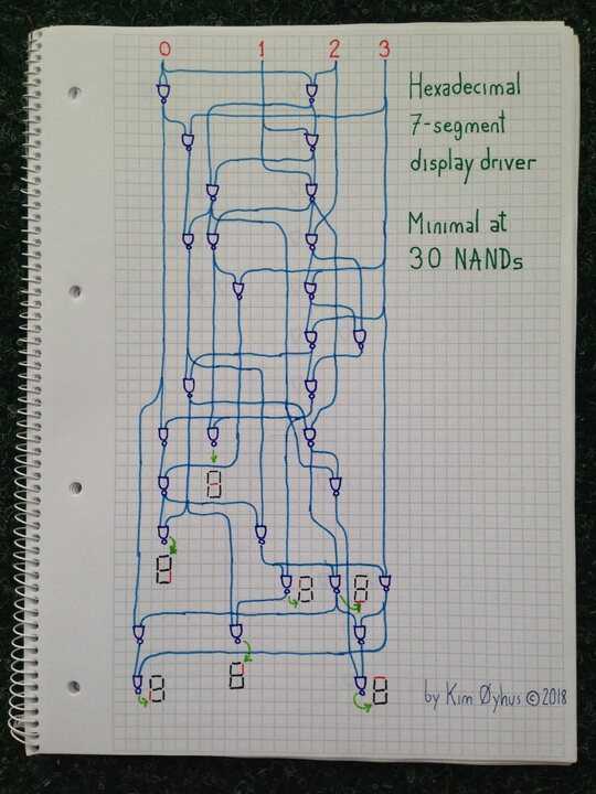
Using ~ for NOT and N for NAND, a computer search (without sharing terms between outputs) finds a solution with 82 NANDs without sharing. Manually looking for sharing terms reduces it to 54 NANDs, and a computer search that includes sharing further reduces it to 37 NANDs. The minimum might be even lower, as the method is certainly not exhaustive.

Here's the program that recreates the above table. Each line is labeled with the NANDS for that output.

#include <stdio.h>

int N(int x, int y) { return 1 & ~(x & y); }

void main(void)
{
    int i0, i1, i2, i3;
    for (i3 = 0; i3 <= 1; i3++) {
    for (i2 = 0; i2 <= 1; i2++) {
    for (i1 = 0; i1 <= 1; i1++) {
    for (i0 = 0; i0 <= 1; i0++) {
            printf("%d %d %d %d : %d %d %d %d %d %d %d\n", i3, i2, i1, i0,
    /* 14 */        N(N(N(i3, N(i2, i1)), N(N(i2, i0), ~i1)), N(N(i2, N(i3, N(i3, i0))), N(i0, N(i3, N(i3, i1))))),
    /* 12 */        N(N(N(i3, i0), N(i2, N(i1, i0))), N(~i1, N(N(i3, i0), N(~i3, N(i2, i0))))),
    /* 10 */        N(N(i0, N(i3, i1)), N(N(i3, i2), N(i1, N(i1, N(~i3, ~i2))))),
    /* 16 */        N(N(N(i2, i1), N(N(i3, i0), N(i2, i0))), N(N(i0, N(i1, ~i2)), N(N(i3, i2), N(N(i3, i1), N(i2, N(i2, i1)))))),
    /*  7 */        N(N(i3, i2), N(N(i2, N(i2, i1)), N(i0, N(i3, i1)))),
    /* 11 */        N(N(i3, N(i2, N(i3, i1))), N(N(i1, N(i2, N(i2, i0))), N(i0, N(i2, ~i3)))),
    /* 12 */        N(N(i3, i0), ~N(N(i1, N(i2, i0)), N(N(i3, i2), N(~i3, N(i2, N(i2, i1)))))) );
    } } } }
}

And here's the output:

0 0 0 0 : 1 1 1 1 1 1 0
0 0 0 1 : 0 1 1 0 0 0 0
0 0 1 0 : 1 1 0 1 1 0 1
0 0 1 1 : 1 1 1 1 0 0 1
0 1 0 0 : 0 1 1 0 0 1 1
0 1 0 1 : 1 0 1 1 0 1 1
0 1 1 0 : 1 0 1 1 1 1 1
0 1 1 1 : 1 1 1 0 0 0 0
1 0 0 0 : 1 1 1 1 1 1 1
1 0 0 1 : 1 1 1 1 0 1 1
1 0 1 0 : 1 1 1 0 1 1 1
1 0 1 1 : 0 0 1 1 1 1 1
1 1 0 0 : 1 0 0 1 1 1 0
1 1 0 1 : 0 1 1 1 1 0 1
1 1 1 0 : 1 0 0 1 1 1 1
1 1 1 1 : 1 0 0 0 1 1 1

And here are the equivalent equations, sharing terms that get it down to 54 NANDs:

    /* 1 */ int z1 = 1 - i1;
    /* 1 */ int z2 = 1 - i2;
    /* 1 */ int z3 = 1 - i3;

    /* 1 */ int n_i2_i0 = N(i2, i0);
    /* 1 */ int n_i2_i1 = N(i2, i1);
    /* 1 */ int n_i3_i0 = N(i3, i0);
    /* 1 */ int n_i3_i1 = N(i3, i1);
    /* 1 */ int n_i3_i2 = N(i3, i2);

    /* 1 */ int n_i0_n_i3_i1 = N(i0, n_i3_i1);
    /* 1 */ int n_i2_n_i2_i1 = N(i2, n_i2_i1);

            printf("%d %d %d %d : %d %d %d %d %d %d %d\n", i3, i2, i1, i0,
    /* 9 */ N(N(N(i3, n_i2_i1), N(n_i2_i0, z1)), N(N(i2, N(i3, n_i3_i0)), N(i0, N(i3, n_i3_i1)))),
    /* 7 */ N(N(n_i3_i0, N(i2, N(i1, i0))), N(z1, N(n_i3_i0, N(z3, n_i2_i0)))),
    /* 5 */ N(n_i0_n_i3_i1, N(n_i3_i2, N(i1, N(i1, N(z3, z2))))),
    /* 8 */ N(N(n_i2_i1, N(n_i3_i0, n_i2_i0)), N(N(i0, N(i1, z2)), N(n_i3_i2, N(n_i3_i1, n_i2_n_i2_i1)))),
    /* 2 */ N(n_i3_i2, N(n_i2_n_i2_i1, n_i0_n_i3_i1)),
    /* 8 */ N(N(i3, N(i2, n_i3_i1)), N(N(i1, N(i2, n_i2_i0)), N(i0, N(i2, z3)))),
    /* 6 */ N(n_i3_i0, ~N(N(i1, n_i2_i0), N(n_i3_i2, N(z3, n_i2_n_i2_i1)))) );

And here's the 37 NAND solution:

    x0fff =  N(i3, i2);
    x33ff =  N(i3, i1);
    x55ff =  N(i3, i0);
    x0f0f =  not(i2);
    x3f3f =  N(i2, i1);
    x5f5f =  N(i2, i0);
    xcfcf =  N(i2, x3f3f);
    xf3f3 =  N(i1, x0f0f);
    x5d5d =  N(i0, xf3f3);
    xaaa0 =  N(x55ff, x5f5f);
    xfc30 =  N(x33ff, xcfcf);
    xd5df =  N(x3f3f, xaaa0);
    xf3cf =  N(x0fff, xfc30);
    xaeb2 =  N(x5d5d, xf3cf);
    x7b6d =  N(xd5df, xaeb2);
    xb7b3 =  N(i1, x7b6d);
    xf55f =  N(x0fff, xaaa0);
    xcea0 =  N(x33ff, xf55f);
    x795f =  N(xb7b3, xcea0);
    xd7ed =  N(xaeb2, x795f);
    xfaf0 =  N(x55ff, x0f0f);
    xae92 =  N(x55ff, x7b6d);
    xdd6d =  N(x33ff, xae92);
    x279f =  N(xfaf0, xdd6d);
    xaf0f =  N(i2, x55ff);
    x50ff =  N(i3, xaf0f);
    xef4c =  N(xb7b3, x50ff);
    x1cb3 =  N(xf3cf, xef4c);
    xef7c =  N(xf3cf, x1cb3);
    xfb73 =  N(i1, x279f);
    x2c9e =  N(xd7ed, xfb73);
    xdf71 =  N(xf3cf, x2c9e);
    xdd55 =  N(i0, x33ff);
    xf08e =  N(x0fff, xdf71);
    x2ffb =  N(xdd55, xf08e);
    x32ba =  N(xcfcf, xdd55);
    xfd45 =  N(x0fff, x32ba);

    printf("%d %d %d %d : %d %d %d %d %d %d %d\n", i3, i2, i1, i0,
            xd7ed, x279f, x2ffb, x7b6d, xfd45, xdf71, xef7c);
    } } } }

AoneOne

Posted 2014-09-11T18:23:44.183

Reputation: 71

2You should have a proud header with "37 NANDs". Your post is too modest without that. – KimOyhus – 2018-10-05T21:53:09.167

4

197 NANDs

Since this is my first logic gates challenge. it is not golfed much, and may not be the smallest solution. I'm not using circuit split here.

A = OR(AND(d, NOT(AND(a, XOR(c, b)))), AND(NOT(d), NOT(AND(NOT(b), XOR(a, c)))))
B = AND(OR(OR(NOT(c), AND(NOT(d), NOT(XOR(b, a)))), AND(d, a)), NOT(AND(AND(d, b), a)))
C = OR(AND(NOT(c), NOT(AND(AND(NOT(d), b), NOT(a)))), AND(c, OR(NOT(d), AND(AND(d, NOT(b)), a))))
D = AND(OR(OR(OR(a, c), AND(AND(NOT(d), NOT(c)), NOT(a))), AND(AND(d, NOT(c)), NOT(b))), NOT(OR(AND(AND(NOT(d), NOT(b)), XOR(c, a)), AND(AND(c, b), a))))
E = OR(AND(NOT(a), NOT(AND(AND(NOT(d), c), NOT(b)))), AND(d, NOT(AND(AND(NOT(c), NOT(b)), a))))
F = AND(OR(OR(d, c), AND(NOT(b), NOT(a))), NOT(AND(AND(c, a), XOR(d, b))))
G = AND(OR(OR(d, c), b), NOT(OR(AND(AND(NOT(d), c), AND(b, a)), AND(AND(d, c), AND(NOT(b), NOT(a))))))
  • 36 NOTs used, 36 NANDs
  • 41 ANDs used, 84 NANDs
  • 19 ORs used, 57 NANDs
  • 5 XORs used, 20 NANDs

If I'm right, my score is 197.


During this challenge, I made a simple JavaScript code to test my gate.

function NOT(a){return !a}function AND(a,b){return a&b}function OR(a,b){return a|b}function XOR(a,b){return a^b}
for(d=0;d<=1;d++){for(c=0;c<=1;c++){for(b=0;b<=1;b++){for(a=0;a<=1;a++){console.log(""+d+c+b+a,
    // Enter your gate here
    // OR(AND(d, NOT(AND(a, XOR(c, b)))), AND(NOT(d), NOT(AND(NOT(b), XOR(a, c)))))
)}}}}

Copy and modify gate, and paste it to your browser's console, or Node.js REPL.

Snack

Posted 2014-09-11T18:23:44.183

Reputation: 2 142