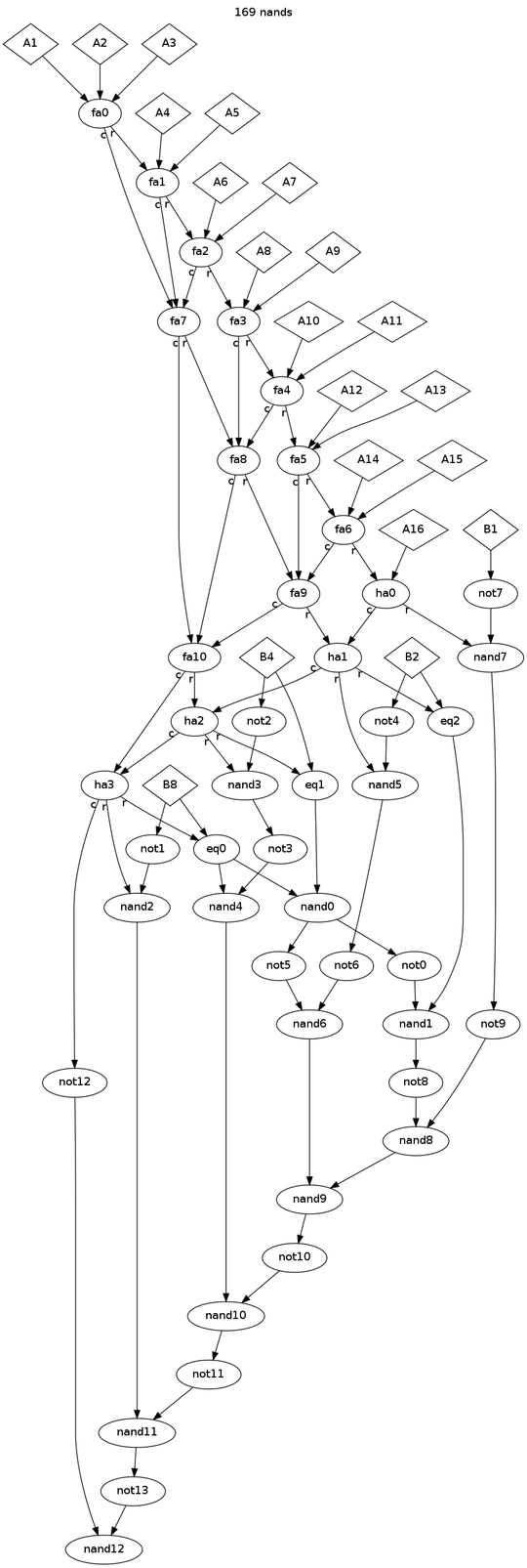
11
A bit-counting comparator (BCC) is a logic circuit that takes some number of counting inputs A1, A2, A3, ..., An as well as inputs B1, B2, B4, B8, ... representing a number. It then returns 1 if the total number of A inputs that are on is greater than the number represented in binary by the B inputs (e.g. B1, B2, and B8 would make the number 11), and 0 otherwise.
For example, for a bit-counting comparator that takes 5 inputs, of which A2, A4, A5, and B2 are set to 1, will return 1 because there are 3 A inputs that are on, which is greater than 2 (the number represented by only B2 being on).
Your task is to create a bit-counting comparator that takes a total of 16 A inputs and 4 B inputs (representing bits from 1 to 8), using only two-input NAND gates, and using as few NAND gates as possible. To simplify things, you may use AND, OR, NOT, and XOR gates in your diagram, with the following corresponding scores:
NOT: 1AND: 2OR: 3XOR: 4
Each of these scores corresponds to the number of NAND gates that it takes to construct the corresponding gate.
The logic circuit that uses the fewest NAND gates to produce a correct construction wins.

So any answer that uses no NAND gates at all will win? That should be easy. Am I allowed to use AND gates with 16 inputs? – r3mainer – 2014-04-08T15:08:38.657
@squeamishossifrage Did you read the question? AND gates add 2 to your score. – Rainbolt – 2014-04-08T15:11:34.777
@squeamishossifrage One
AND== twoNAND– Timtech – 2014-04-08T15:38:19.093@Timtech Then why the requirement to use "as few NAND gates as possible"? – r3mainer – 2014-04-08T15:45:23.943
1@squeamishossifrage, "using only NAND gates". The scores for other gates are the minimum number of NAND gates required to build them; essentially it's defining some convenience macros. – Peter Taylor – 2014-04-08T15:49:11.497
@PeterTaylor Aaaah, I see. So gates with 16 inputs are fine, then? – r3mainer – 2014-04-08T15:51:35.300
@squeamishossifrage None of the gates listed take 16 inputs. – Rainbolt – 2014-04-08T15:57:44.723
@Rusher Here's a 13-Input NAND gate: http://www.classiccmp.org/rtellason/chipdata/dm74als133.pdf
– r3mainer – 2014-04-08T16:03:42.833"...16 A inputs and 4 B inputs (representing bits from 1 to 8)..." How come there are 8 bits from only 4 B inputs? – user80551 – 2014-04-08T16:16:56.720
@user80551 How many base ten digits do you need to represent the numbers zero through nine? Only one I hope. – Rainbolt – 2014-04-08T16:18:45.513
"because there are 3 lights on" -- where do lights come into the problem ? – Paul R – 2014-04-08T16:28:05.317
@Rusher I'm assuming each input is one bit. Oh wait, is it
sum(total number of A-bits on)>int_representation(B)? Then the question is a bit unclear – user80551 – 2014-04-08T16:54:22.677@PaulR Lights are commonly used analogies for things that can be OFF or ON. – Rainbolt – 2014-04-08T16:59:05.597
1@user80551 You need 16 bits to tell if 16 bits are ON or OFF. You need 4 bits to represent a 4 bit number. The number of ON bits must be greater than the 4 bit number. I don't really understand why that is so difficult. See the part of the question that says "total number of A inputs that are on is greater than the number represented by the B inputs."? – Rainbolt – 2014-04-08T17:01:33.977
@user80551 It is indeed. – Joe Z. – 2014-04-08T17:52:12.640
@PaulR I tend to think of light switches when designing these logic gate problems. Sorry if I made a mental typo that made it incomprehensible. – Joe Z. – 2014-04-08T17:54:16.820